Welcome to the documentation section! Here you can find more information about projects Badge.Team was involved in.
Looking for information about a specific badge? Check out the badges section.
Want to help improve the documentation?
All resources on this site are works-in-progress. Please let us know if you find
any errors or run into corner that could be explained more clearly by opening
an issue or pull
request in the documentation
website repository.
1 - Badges
Badge.Team badges
These are the badges where Badge.Team volunteers were involved in during their creation, either by helping with hardware development or by providing firmware. You can click on each of the badges to go the corresponding documentation section.
ESP32 based
Other badges
The CCC camp 2019 “CARD10” badge
The CARD10 uses the hatchery as its app repository. For all other details about this project (the hardware, firmware and API) please have a look at the CARD10 project over at the CCC website.
1.1 - Bornhack 2026 badge
Introduction
The BornHack 2026 badge is the Cyber Ægg. It is an egg-shaped, low-power hacker badge, inspired by the Tamagotchi of the 1990s. One battery charge runs the badge for the full BornHack camp. A long-range LoRa mesh keeps you connected to everyone else on the field.
Under the playful shell is a serious radio computer. A Nordic nRF52840 drives a 1.54 inch black, red and white e-paper display. The badge talks Bluetooth Low Energy to your phone, and it emulates an NFC tag on its back. A dedicated SX1262 LoRa radio connects the badge to the wider MeshCore network. Between messages, BornPets entertains you. BornPets is a virtual pet with a set of mini-games.
Front (display and buttons) and back (nRF52840, USB-C connectors, NFC coil).
Expansion connector pinout
The board has an I²C expansion connector of the QWIIC type. We made a design mistake: the 3.3 V and the GND signals are swapped. Before you connect a QWIIC peripheral, make a corrected cable and use that.
Features
Egg-shaped badge, inspired by the classic Tamagotchi
Nordic nRF52840 microcontroller (BLE, USB and NFC)
1.54 inch 152 × 152 black, red and white e-paper display
SX1262 LoRa radio, part of the MeshCore mesh network
Bluetooth Low Energy companion connection to the MeshCore app
NFC tag on the back, for location games and station taps
5-way joystick, Select, Execute and Cancel buttons, RGB LED and a piezo buzzer
USB-C for charging and for file transfer with drag and drop
Start with the Getting started guide. The Games page describes the virtual pet. The Hardware page tells you what is inside the badge.
Update your badge from the browser
The Flash page installs the firmware and the badge’s asset files from a Chromium-family browser over USB. You need no toolchain and no command line. The page offers the standard firmware and the Community Edition, a fork with more BornPets mechanics.
Source code
The Cyber Ægg is open source. The hardware design and the firmware are on Codeberg:
Bad Apple!! — annejan/aegg-apple, the animation on the e-paper panel with the tune on the buzzer
Hardware sponsors
Nordic Semiconductor sponsored their low power yet very capable and fast NRF52840 microcontroller with Bluetooth Low Energy and NFC, making it possible for us to build a device that runs on one battery charge, the whole camp long!
ALLNET China is our production partner, they take care of sourcing most components and oversee the production process in China, saving us a lot of work and potential headaches and allowing us to focus on the product!
Procolix sponsored the SX1262 LoRa radio chips, converting the badge into a capable LoRa communications device. Check out their managed hosting solutions for a truly sovereign cloud built on European open source solutions!
deFEEST sponsored part of the badge hardware, helping us get the components we needed to build it. Find out more at defeest.nl!
Mollerup Automation sponsored the 3D printed housing for the badge. They are automation, robotics and PLC specialists from Odense, Denmark — see mollerup.info!
1.1.1 - Getting started
This guide takes you from the unboxing of the BornHack 2026 Cyber Ægg badge to the first use. It takes a few minutes.
First power-on
A new badge runs a factory self-test on the first start. The badge shows a FACTORY TEST screen with a small PASS/FAIL grid, and then ALL PASS. After that, the badge starts the application directly at every start. The self-test does not run again, unless you erase the firmware.
The first start then plays a sponsor slideshow. It shows the event logos and then the badge-sponsor logos, a few seconds each. The slideshow plays only once. To see it again, select Main → Badge sponsors.
The LED sequence at every start is:
Pulsing orange — the hardware initializes
Pulsing blue — the display and the LoRa radio start (about 13 seconds)
One green flash — the badge is ready
The badge then shows the Main screen.
Controls
The badge has a 5-way joystick on the left and two thumb buttons on the right:
Control
Action
Execute / joystick press (Fire)
Select or activate
Cancel
Go back or dismiss
Up / Down
Move the cursor in the current screen
Left / Right
Go to the next top-level screen
Top-level screens
The interface is a carousel. Left and Right move through the top-level screens:
Screen
What it is
Game
BornPets — the virtual pet, the mini-games and the hatchery
Main
Root menu: Bornagotchi · Settings · About · Badge sponsors
PMs
Inbox for private mesh messages
Channel
Group or room mesh chat
Adverts
Mesh adverts the badge heard recently
Tokens
The NFC tokens you collected
Clock
Digital or analog watch face, and the alarm
Calendar
Month grid and the timeline for each day
Name
Large conference-badge name view
My QR
Your mesh identity as a QR code, to share with other badges
Pair with the MeshCore app
The badge speaks the MeshCore companion protocol over Bluetooth Low Energy. Install the MeshCore app on Android or iOS. You can also open https://app.meshcore.nz/ in a browser with Web Bluetooth, such as Chrome or Edge on desktop or on Android.
Make sure that Bluetooth is on. Main → Settings → Bluetooth must show BLE: ON.
Scan for devices in the app. The badge advertises as Cyber Ægg XXYY. XXYY is four hex characters, unique to your badge.
The phone shows a passkey prompt, and the badge shows a 6-digit passkey on its display. Type that number into the phone.
After the bond, the app can set the clock, manage contacts, send and receive mesh messages, and change the LoRa preset.
Set the time
The badge has no real-time clock with a backup battery. The clock therefore returns to “not set” at every start. You can set it in two ways:
With the MeshCore app. Connect over Bluetooth, and the app sends the time of your phone to the badge.
Near a synchronized repeater. A known-good mesh repeater advertises its time regularly, and your badge takes it automatically.
Set your timezone once, under Main → Settings → Timezone. The badge keeps that setting.
Charging
Connect any USB-C cable to the badge to charge it. The battery icon on the screen shows the charge state. There is no separate charge LED.
Two effects look like faults, but they are correct. If the charge symbol disappears while USB stays connected, the charge is complete. The symbol comes back when the cell drains. The battery icon can also be up to a minute behind, because the badge measures the battery only every 60 seconds.
USB drag-and-drop
When you connect USB-C, the badge appears as a small drive with the name CYBR<4 hex>. You can put these files in its root:
File
Effect
ALARMS.ICS
iCalendar file — imports alarms and calendar events
030000.PCX … 030009.PCX
Sponsor slides for the splash carousel
<6 hex>.PCX
Game sprites
PETS.CFG
Adds or renames pets, with their sprite PCX files — see Games
BORNPETS.CFG
Replaces the BornPets game balance
LUT.CFG
Custom e-paper waveform (advanced — a calibrated display LUT)
After you copy files, restart the badge with a new connection of the USB cable. The changes then take effect.
LUT.CFG is an advanced change. It replaces the built-in display waveform of the panel with a calibrated one, for example for a faster refresh. If a custom LUT gives a bad image, hold Fire (the joystick press) during the start. The badge then uses the safe built-in waveform for that start. Delete the file, or correct it. The badge rejects a damaged LUT.CFG, or one for a different panel, automatically.
Firmware update
The Flash page is the easiest method. It writes the firmware and the badge’s asset files from a Chromium-family browser. You install no toolchain.
To do it by hand, enter the bootloader (DFU) mode first. Slide the ON/OFF switch at the top left of the front off, then back on, while you hold Execute. The LED then blinks red. The battery keeps the badge running, so a disconnection of USB does not restart it. You can then write a new firmware image with dfu-util:
dfu-util -d 1915:521f -D cyber-aegg.bin
The firmware is open source, and we build it with Rust and Embassy. See Ranzbak/bornhack-firmware-2026 for the source, the build instructions and prebuilt images.
1.1.2 - Quick reference
This is a one-page cheat sheet for the Cyber Ægg. Print it and put it under the strap.
Game → Main → PMs → Channel → Adverts → Tokens → Clock → Calendar → Name → My QR
LED meanings
Color
Meaning
Pulsing orange
Start — the hardware initializes
Pulsing blue
The display and LoRa start (about 13 s)
One green flash
The start is complete
Red flicker
The screen refreshes
Blue flicker
The badge writes to the USB drive
Blinking green
The badge erases the contacts
One red, green or blue flash
A person pinged you over the mesh (blinkme)
Power-on combos
Hold the button while you start the badge. Slide the ON/OFF switch at the top left of the front off, then back on. The battery keeps the badge running, so a disconnection of USB does not restart it.
Hold
Result
Execute
USB firmware update (DFU mode)
Fire (joystick press)
Forces the safe e-paper waveform, and ignores a bad LUT.CFG for that start
Execute + Cancel + Fire
Factory reset (about 40 s — erases the data and the settings)
If the application slot is empty, the badge enters DFU mode without a button.
USB drag-and-drop
Connect USB-C. The badge mounts as the CYBR<4 hex> drive.
File you put on the drive
What it does
ALARMS.ICS
Imports alarms and calendar events
030000.PCX … 030009.PCX
Sponsor slides
<6 hex>.PCX
Game sprite asset
PETS.CFG
Adds or renames pets, with sprite PCX files
BORNPETS.CFG
Custom pet balance (KEY=VALUE)
LUT.CFG
Custom e-paper waveform (advanced)
Restart the badge after you copy the files.
Firmware update (DFU)
dfu-util -d 1915:521f -D cyber-aegg.bin
The bootloader LEDs in DFU mode are: a red blink for idle, solid blue during the write, solid green when the write is complete. Then power cycle the badge.
Charging
USB-C in any port charges the badge. There is no separate charge LED. The battery icon on the watch face and in the status bar shows the level.
1.1.3 - Mesh & messaging
The badge has a LoRa SX1262 radio, and it speaks the MeshCore mesh protocol. Other badges, MeshCore phones and separate repeaters all appear as peers. Four carousel screens use the mesh: PMs, Channel, Adverts and My QR. The Contacts list holds the peers behind them.
Getting on the same network
Three things must be the same on every badge in the local mesh:
LoRa preset. This is the frequency, the bandwidth and the spreading factor. The default preset is BornHack 2026, and the firmware includes it. Change it under Main → Settings → LoRa Radio.
Public channel key. The preset shares this key automatically.
Antenna. Make sure that the LoRa antenna is connected.
If you see no adverts from other badges after a minute, check the preset first.
Adverts
Every badge, phone and repeater on the mesh broadcasts an advert at regular intervals. The advert holds the public name, the identity hash and the capabilities. Your badge lists the adverts it receives on the Adverts screen.
Key
Action
Up / Down
Move through the advert list
Execute / Fire
Saves the selected advert as a contact
Cancel
Go back
Left / Right
Go to the next carousel screen
Private messages (PMs)
The PMs screen is your private inbox. Each row is a peer that sent you a message.
Marker
Meaning
●
Heard less than 5 minutes ago
*
Favorite
+
Discovered, but not saved as a contact
R
Repeater
#
Room or channel server
S
Sensor
Use Up and Down to move through the list. Use Execute / Fire to open a thread or to start a reply. Use Cancel to go back. A reply uses the keyboard on the screen. Move the joystick to select a character, press Execute to accept it, and press Cancel to delete the last character. About 70 emoji are available.
RAM-only
The inbox holds up to 32 messages from 16 peers, in RAM. The badge keeps saved contacts and their threads through a restart. Messages from peers you did not save disappear when the badge restarts. Save every peer you want to keep.
Channels (group chat)
The Channel screen is the group chat, or room chat. It uses the same protocol with a broadcast scope. Each row is a channel, for example the default Public channel in the preset. The controls are the same as on the PMs screen. Every badge with the same preset hears every message in a public channel.
My QR
The My QR screen shows your mesh identity as a QR code. Show the code to another MeshCore phone or badge for an immediate pairing. The other device does not have to wait for an advert.
Contacts
The Contacts list shows every peer the badge heard or knows: nearby strangers, saved friends, repeaters and rooms. Open it under Main → Bornagotchi → Contacts, or from the Adverts screen.
Key
Action
Up / Down
Move through the list
Up on the top row
Opens the filter: All, Favorites, People, Repeaters, Rooms or Sensors
Execute / Fire
Opens a popup: PM · Info · Add · Save / Unsave · Forget
Cancel
Go back
The popup actions are:
PM. Opens the message thread.
Info. Shows the hex identity prefix, the last-heard time and the advert capabilities.
Add / Save. Writes the contact to flash, so it survives a restart.
Unsave. Removes the contact from flash. It stays in the discovery cache until the next restart.
Forget. Removes the contact immediately, also from the discovery cache.
Save what you want to keep
The discovery cache holds up to 32 unsaved peers in RAM. It is empty after every restart, until new adverts arrive. A peer you did not Save is gone after a restart, together with its message history. When the cache is full, the badge removes the oldest unsaved entry for a new advert.
Pinging & visibility
When another badge pings you with the mesh blinkme command, your LED flashes shortly in the requested color. This helps you find friends in a crowd. Your badge also sends its own adverts, so other people can see you.
Battery note
The LoRa radio uses the most battery power. To save power, mute the notification sounds under Main → Settings → MeshCore. The e-paper display uses no power after it shows an image.
Using your phone instead
You can also chat from your phone. Install MeshCore on Android or iOS, or open https://app.meshcore.nz/. Then pair the phone over Bluetooth. See Getting started. After the bond, the app gives you the contacts, the chat and the settings.
1.1.4 - NFC & tokens
The back of the badge has an NFC antenna. Touch a phone or a station reader against it to interact. You do nothing on the badge, because it is always ready.
Two things happen on a tap
A phone reads your broadcast profile
Any standard NFC reader, such as the built-in reader of Android or iOS, sees your broadcast profile. The default profile is the badge’s own documentation page, https://badge.team/docs/badges/bornhack-2026/. You can replace it with your own vanity URL, a vCard or another record. See Set your own broadcast data. A tap with the reader of the operating system only reads the profile. It is harmless.
BadgeCtl runs a station command
A phone with the BadgeCtl companion app and the correct event key sends signed commands to the badge. The event stations use these commands, and they improve the statistics of your BornPet:
Command
Effect on your BornPet
more food
Sets hunger to 0
more drugs
Sets sick to 0
more inspiration
Sets drained to 0
sleep like a bear
Sets tired to 0
A short message on the badge confirms the result. Each command has a cooldown of 5 minutes. A second tap in that period does nothing.
Station commands need an active game. Select a pet first. The egg countdown counts as an active game. If your pet left, start a new egg. The badge ignores a tap when no pet is active.
Tokens
Tokens from station taps and from other badges go to the Tokens screen in the carousel. The badge collects many tokens and keeps them until the next start. The list is a record of the stations and the badges you tapped during the camp.
When a person pushes a token: to your badge, the badge shows it for about 10 seconds. The badge then broadcasts your own profile again. A pushed token cannot replace your profile.
Set your own broadcast data
The default documentation URL is not permanent. The badge can broadcast any record you like. Use an NFC writer app on your phone, such as NFC Tools, and write to the back of the badge:
Vanity URL. Write a URL or URI record, for example annejan.com. A Text record set:https://your.link also works, for writer apps that write text only.
vCard. Write a Contact or vCard record. Phones that tap your badge then get your contact card.
Wi-Fi, or any other record. The badge serves it without a change.
The rule is simple. The badge keeps what you write, and the record survives a restart. The one exception is a token: record, which goes to your Tokens screen instead. Keep the record short. The limit is about 127 bytes, which is enough for a URL or a small vCard. The badge also cuts a long URL in the set: text form to about 118 characters after the scheme. For a longer URL, write a plain URI record, or use a link shortener.
NFC has no erase function that returns the factory default. An empty write, or the “format tag” function of a writer app, does not restore the built-in documentation URL. It keeps your current profile, or it stores the empty record. To change the broadcast, write the new record over the old one.
This function is unauthenticated. Any person who touches your badge with a writer app can change the record. The badge is in your pocket, so control physical access to it.
What the reader side needs
The badge is always ready. The reader needs two things:
The BadgeCtl app.
The correct Ed25519 private key in the app. BornHack staff hold this key for the official stations.
Other NFC reader apps cannot send these commands, because they do not have the key. They see only the public URL.
Running your own station
You can run your own station. Build the badge firmware again with your own Ed25519 public key. Then sign the commands with your private key in your reader app. The protocol specification, the wire format and a signing recipe in Kotlin, Python and Rust are in the firmware’s NFC_README.md.
How it works (hardware)
The nRF52840 includes an NFC tag PHY. It drives a coil on the PCB of about 2.8 µH, tuned with capacitors to 13.56 MHz. The PHY supports tag mode only, not reader mode. See the Hardware page.
1.1.5 - Clock, alarm & calendar
Three apps use the watch slots of the carousel: Clock, Alarm and Calendar. You open the Alarm from the Clock.
Clock
The Clock has two watch faces, digital and analog. A small bell icon in the header appears when an alarm is on.
To open it: press Left or Right until the badge shows the Clock screen.
Key
Action
Up / Down
Changes between the digital face and the analog face
Execute / Fire
Opens the alarm editor (slot 0)
Left / Right
Goes to the next or the previous carousel screen
Setting the time
The badge has no backup battery for its real-time clock. The clock therefore returns to None at every start, and it shows “Clock not set” until you set it. You can set it in two ways:
With the MeshCore app over Bluetooth. The phone sends its time. This is the easy method.
With a mesh time advert. Stay near a synchronized LoRa repeater, and the badge takes the time over the air. The badge accepts a time over the air only from a trusted source. That is a repeater or companion advert with a verified signature, or a channel that you hold the key for. Other badges near you cannot set your clock.
Set the timezone once, under Main → Settings → Timezone. The badge keeps that setting through a restart. The default is +2, which is CEST for BornHack.
No seconds hand
A time from BLE overrides the refinement over the air until the next restart. The watch face has no seconds hand, because the e-paper refresh is too slow for one.
Alarm
Press Execute / Fire on the Clock screen to open the alarm editor.
Key
Action
Up / Down
Moves between the fields: Hour, Minute, Days, Tone, Enabled
Execute / Fire
Enters or leaves the edit mode of a field
Cancel
Returns to the watch face
The Days field steps through Daily, Weekdays, Weekends, None and Custom. The Tone field has ten built-in tunes: Beep, Imperial March, Rickroll, Pink Panther, Sandstorm, Startup, Trololo, Daisy Bell, Nokia and Samsung.
At the alarm time, the buzzer plays the selected tone up to five times, with 8 seconds between them. Any button press stops the alarm. If you do nothing, the alarm stops after about 32 seconds.
Set the clock first
An alarm sounds only when the clock is set. After a restart, pair the badge or wait for a time advert. Until then, the alarm does not sound.
Calendar
The Calendar is a month grid with a timeline for each day. It shows the iCalendar events you imported.
To open it: press Left or Right to the Calendar screen, to the right of the Clock. The grid appears without a cursor. Press Execute / Fire to enter the active mode.
Active mode:
Key
Action
Up / Down
Moves the cursor 7 days, one week
Left / Right
Moves the cursor 1 day
Execute / Fire
Opens the timeline of the day
Cancel
Returns to the passive view
Day detail (timeline):
Key
Action
Up / Down
Moves 1 hour
Left / Right
Moves a long event title horizontally
Execute / Fire
Shows the full day list, with all events
Cancel
Returns to the month view
Loading events
The badge imports events at the start, from a file with the name ALARMS.ICS in the root of the USB drive:
Connect the USB-C cable to your computer.
Open the drive with the name CYBR<4 hex>.
Copy your .ics file to the root, with the name ALARMS.ICS.
Eject the drive.
Restart the badge. Slide the ON/OFF switch at the top left of the front off, then back on.
The badge stores up to 31 events. It cuts an event that covers more than one day. The event then ends at 23:59 on the first day, because the e-paper view draws no event over more than one day. All events are in RAM only, and the badge imports them again from ALARMS.ICS at every start.
Import limits & quirks
The parser is minimal on purpose. If events are absent or wrong, one of these limits is usually the cause:
File size: 16 KiB maximum. The parser cuts the rest of the file, in the middle of an event, without a message. A full conference program is larger than this. Cut it first with the firmware’s scripts/strip_ics.py. That script removes DESCRIPTION, UID and similar fields, and it accepts --from, --to and --max to select a range.
31 events maximum. The import stops at the limit without a message. Later events in the file never appear.
No recurrence. The parser ignores RRULE. A repeated event imports as its first occurrence only. Export an expanded ICS file with one entry for each occurrence. The BornHack program is already expanded.
No all-day events. The parser drops a DTSTART with a date and no time, without a message. Give the event a real start time.
ASCII only. The parser removes non-ASCII characters from titles. It does not transliterate them, so Æ, accented letters and emoji disappear.
Timezones. The parser shifts only timestamps with the Z suffix, which are UTC, to local time. It always uses the built-in default of UTC+2, which is correct for BornHack, because the import runs before the badge applies your saved timezone. The parser takes floating times and TZID= times without a change. Export in UTC if you are not sure.
An event that fired disappears from the Calendar until the next start. Imported events are single-shot alarms. After one fires, the grid and the day view no longer show it. A restart imports everything again.
Changes take effect at the start only. Replace ALARMS.ICS, eject the drive correctly, then power cycle the badge.
1.1.6 - Games
The Game screen runs BornPets, a virtual pet in the style of the Tamagotchi of the 1990s. It also holds a set of mini-games. You start the mini-games from the pet’s Play menu.
BornPets
Hatch a snail or a cat. Then keep the pet fed, healthy, rested and entertained.
Hatching
The first time you open the Game screen, the badge shows the hatchery. Press Execute / Fire to start. Select a pet from the roster. The built-in pets are Bartholomeus, Cat and Slug. The egg then hatches in about one minute. After the hatching, give your pet a name of up to 12 characters, with the keyboard on the screen. The badge keeps the pet through a restart. You can rename the roster, and you can add your own pets. See Custom pet roster below.
Stats
Your pet has stats that increase with time. A high value is bad for the pet. Watch these stats:
Stat
Fix with
Notes
Hunger
Feed
The pet gets hungry, and the other stats get worse
Tired
Rest or sleep
Use Hibernate for a long sleep
Drained
Play, or a mini-game
The pet has no inspiration. Play also clears “miserable”
Sick
Heal
Use this when the sick icon appears
Miserable
Play
The other stats then get worse faster, so correct this early
The stats interact. When several stats are bad, the pet becomes miserable faster, and a miserable pet makes every other stat worse. Stay ahead of this spiral.
Controls
Key
Action
Up / Down
Changes between the top row (the actions) and the bottom icon row
Left / Right
Moves along the current row
Execute / Fire
Activates the selected icon
Cancel
Goes back
Hibernate
Before you store the badge for more than a few hours, open the action menu and select Hibernate. The stats then freeze until you wake the pet. If you store the badge without hibernation, the stats continue to decay, and the pet can starve before you find the badge again.
Game modes
There are two difficulty settings, under Main → Bornagotchi → Mode:
Classic. The original balance of the badge.
Casual. About half the decay speed, and more relief for each action. Use this if you do not want to care for the pet often.
The badge keeps the setting in flash. A * next to the mode name means that the change waits. Restart the badge to apply it.
Turning the pet off
You can remove the pet. Main → Bornagotchi → Disable Game hides the whole Game screen from the carousel. The badge keeps this setting through a restart, and the label changes to Enable Game. While the game is off, an NFC station tap can no longer open the pet. Select Enable Game to get the pet screen back.
Mini-games
Open the Play menu in the bottom row of BornPets and select a game. Each win lowers the drained stat, and it does not raise hunger. The games are therefore free entertainment. Cancel always leaves a mini-game.
Game
Goal
Tic-Tac-Toe
Draw against the computer, or win (Normal or Impossible difficulty)
Lights Out
Switch a 5×5 grid until every light is off
Nim
Force the computer to take the last stick
Maze
Reach any border exit of an 18×18 maze
Black Hole
Beat the sum of the AI on a pyramid of 21 cells
Triple Born
A merge game in the style of Triple Town, on a 6×6 board
BornJeweled
An accessible match-3 game with a limit of 30 moves
In a game, the joystick moves the cursor. Execute / Fire places or selects. Cancel returns to the Play menu.
Make your own pet
You can build a companion that is not a snail or a cat. The CyberÆgg Pet Maker is a sprite and animation editor for BornPets, and it runs in the browser:
Start from a preset (Bartholomeus, Cat or Slug), or from a Blank canvas.
Draw each animation frame with the badge’s palette: black, red, white and transparent. White is the e-paper background, and transparent means that the badge draws nothing.
Preview the animation states, for example Idle, with controls for the speed and the onion skin.
Change the game balance (BORNPETS.CFG), which sets how fast the stats decay and recover.
Select Download ZIP to get all the files for the badge.
Installing a custom pet
The badge shows a USB drive when you connect USB-C. See Getting started. Unpack the export of the Pet Maker. Copy the sprite files to the root of the CYBR<4 hex> drive, together with PETS.CFG and, if you made one, BORNPETS.CFG. Then restart the badge.
Hand-editing sprites (GIMP etc.)
The badge accepts one specific PCX format: 2 bits per pixel, one plane, RLE. Editors such as GIMP export a PCX with 16 or 256 colors instead, and the badge skips those files without a message. The firmware’s scripts/ folder has helpers for this problem:
fix_badge_pcx.py writes a PCX with the wrong depth, for example a 4 bpp or 8 bpp GIMP export, back to the badge’s 2 bpp format. It keeps the dimensions.
check_badge_pcx.py checks a file before you copy it. You then find a bad export on your computer, not on the badge.
Custom pet roster: PETS.CFG
PETS.CFG is the pet roster in the “Choose your Pet” screen. It is a plain-text file with one PREFIX=NAME on each line. You can edit it without a new firmware:
# --- current pets (rename if you like) ---
0=Bartholomeus
1=Cat
2=Slug

# --- add your own (needs 05xxxx.PCX / 06xxxx.PCX sprites) ---
5=Dragon
6=Ghost
PREFIX is the sprite-prefix byte of the pet, in decimal:
0, 1, 2 are the built-in pets. A line for one of these renames it.
3, 4 are reserved for sponsors and menu icons, and the badge ignores them.
5 to 7 are your own pets.
NAME is up to 16 ASCII characters.
The sprites of a pet are the PPAAFF.PCX files on the badge. PP is the prefix, AA is the animation part, and FF is the frame. The firmware counts the PCX files that are present, for example 050100 to 050104 for five idle frames. There is therefore no fixed frame count and no header to maintain. Export the sprites at the prefix of the pet from the Pet Maker, and copy them to the drive next to PETS.CFG. The firmware ignores lines that start with #, and reserved or damaged lines.
Custom balance: BORNPETS.CFG
To change only the difficulty, and not the sprites, copy a plain-text BORNPETS.CFG file to the root of the badge’s USB drive. Write one KEY=VALUE on each line:
# speed up hunger decay, slow down the drained stat
HUNGER_RATE=4
DRAINED_INTERVAL=180
Eject the drive and restart the badge. While a configuration is active, a small * appears after the name of the pet. To return to a preset, delete the file and restart the badge. The Pet Maker can write this file for you. The firmware’s USER_GAMES.md documents every key and its range.
Three points are important:
Changes take effect at the start only. Eject the drive correctly, so that the computer writes the data. Then power cycle the badge. If no * follows the name of the pet, the badge applied no override.
The parser is silent. It skips an unknown key. It also drops the whole line for a value that is not a plain whole number, so no units, no decimals and no minus sign. It shows no error on the screen.
The documented “reasonable range” is advice, not a limit. The firmware limits a value only to the range of the integer type. HUNGER_RATE=1000 really fills hunger about 300 times faster, and your pet starves before you disconnect the cable. If a large value damaged your pet, delete the file and restart the badge to return to the preset.
1.1.7 - Hardware
The Cyber Ægg is a low-power LoRa badge around a Nordic nRF52840 microcontroller. The design goal is one battery charge for the full week of BornHack. The hardware and the firmware therefore keep the power consumption low.
The design is a prototype at this time. Some of the RF circuits, for NFC, LoRa and Bluetooth, still have U.FL and IPEX connectors, which make the tuning easier. We also did not fully characterize the antennas on the PCB. Treat this design as beta. Do not order your own boards yet.
Overview
Component
Part
Interface
Microcontroller
Nordic nRF52840
—
Display
1.54 inch black, red and white e-paper, 152 × 152, SSD1675 / SSD1675B controller
SPI
LoRa radio
Semtech SX1262
SPI
Bluetooth Low Energy
Built-in radio of the nRF52840
—
NFC
NFC tag PHY of the nRF52840, with a coil on the PCB
—
Input
5-way joystick, Execute and Cancel buttons
GPIO
Feedback
RGB LED, piezo buzzer
GPIO / PWM
Power
Li-ion battery, USB-C for power and data, ON/OFF slide switch
—
Expansion connector pinout
The board has an I²C expansion connector of the QWIIC type. We made a design mistake: the 3.3 V and the GND signals are swapped. Before you connect a QWIIC peripheral, make a corrected cable and use that.
Display
The badge has a 1.54 inch tri-color e-paper display in black, red and white. The resolution is 152 × 152 pixels, and an SSD1675 or SSD1675B controller drives it. E-paper stays readable in bright sunlight at the camp, and it uses no power to hold an image. Both properties help the battery goal of one week.
The panel uses the waveform LUT in its own OTP memory by default. Advanced users can replace that waveform with a calibrated one, for example for a faster refresh. Copy a LUT.CFG file to the USB drive. See the firmware’s LUT.md. You can make a waveform with the ssd1675-calibration tool. If you hold Fire during the start, the badge always uses the safe built-in waveform.
Manual input
The Tamagotchi egg toy of the 1990s inspired the Cyber Ægg, so the buttons have the same names:
Button
Function
Select
Moves through the menu options
Execute
Starts the option under the cursor
Cancel
Cancels the current operation
The Select button is a 5-way joystick with a press action, which makes the navigation easier.
Bluetooth
The nRF52840 provides Bluetooth Low Energy directly. It works in the 2.4 GHz band, and it uses an antenna on the PCB. That antenna comes from a Texas Instruments reference design in the standard KiCad 9 library. For the details, see the TI application note SWRA228.
LoRa
A dedicated Semtech SX1262 radio provides the long-range connection. The matching and balun circuit follows the Semtech application note AN1200.54. The LoRa antenna is a Texas Instruments design, documented in SWRA416. On the network side the badge speaks MeshCore, so it joins the camp mesh immediately.
NFC
The nRF52840 includes an NFC PHY. It drives a resonant circuit: a coil on the PCB of about 2.8 µH, with tuning capacitors. This tank circuit is matched to 13.56 MHz. The nRF52840 supports tag functionality only, not reader mode. The firmware uses the tag for location games and station taps.
Expansion connector
The board has an I²C expansion connector of the QWIIC type. We made a design mistake: the 3.3 V and the GND signals are swapped. Before you connect a QWIIC peripheral, make a corrected cable and use that.
Fix the cable — cross the two power wires
A standard QWIIC or JST-SH 4-pin cable carries GND · 3V3 · SDA · SCL. The badge swaps 3.3 V and GND, so a standard cable sends reversed power to your peripheral. Do not use one.
To make a corrected cable, swap the two power wires at one end only. Leave the other end standard, so that it still fits the peripheral.
At the badge end of the cable, lift the small locking tab of the JST-SH housing. Then pull the GND and the 3V3 contacts out carefully, with a fine pick or with tweezers.
Swap the two contacts. The wire from the GND slot goes into the 3V3 slot, and the wire from the 3V3 slot goes into the GND slot. The two data wires, SDA and SCL, stay in position.
Push both contacts back until they click, and make sure that nothing is loose.
The data lines do not change, so you move only the two power contacts. Mark the corrected cable, so that you do not use it as a standard one. As an alternative, cut the red (3V3) and the black (GND) wires and solder them crossed. You can also keep one cable for the badge only.
The connector on the badge should have been compatible with QWIIC. QWIIC is a standard I²C connector, used by many SparkFun breakout boards and by boards from other suppliers. The board has two 10 kΩ pull-up resistors. You can also enable the internal pull-ups of the nRF52840 when the bus capacitance is high.
The firmware can also drive an optional Nicolai-Electronics I²C keyboard on this bus, for names and mesh messages. Connect the keyboard with the corrected cable, and the text entry uses the physical keys. Shift and Alt are one-shot toggles, and the alt-symbol layer matches the silkscreen. Without a keyboard, the badge uses the joystick picker on the screen automatically.
Power
A LiPo battery powers the badge, and USB-C charges it. An ON/OFF slide switch at the top left of the front disconnects the battery power. Slide the switch off and back on to power cycle the badge. The battery keeps the badge running when USB is disconnected, so this switch is the only way to restart it. Hold Execute while you switch the badge on to enter DFU mode for a firmware write.
1.1.8 - FAQ & troubleshooting
These are the answers to the questions people ask most often about the Cyber Ægg. If no answer helps, report a bug. The bottom of this page tells you where.
General
The badge does not wake up, and the display stays empty.
Connect USB-C. If the LED does not blink, hold Execute while you connect the cable, and write the firmware again with dfu-util. See Getting started → Firmware update.
After a firmware write or a factory reset, the badge shows the factory test, then a “ready to ship” screen, and it stops there.
This is correct behavior. After a self-test with all tests passed, the badge sets its pass flag, draws the ship screen and stops. The green LED pulses. Power cycle the badge once more. The second start skips the test and runs the application.
The badge shows “Battery voltage critical” at the start, and it goes no further.
The cell measured less than 3.0 V at the start, so the firmware stops to protect the cell. The hardware controls the charge, and it continues. Leave USB connected for some time, then power cycle the badge by hand. The badge does not restart itself from this screen.
The clock resets at every start.
This is expected, because the badge has no RTC with a backup battery. Pair the badge over Bluetooth with the MeshCore app once per start, or stay near a synchronized mesh repeater. The badge accepts a time over the air only from a trusted source. That is a repeater or companion advert with a verified signature, or a channel that you hold the key for. Other badges near you cannot set your clock. A pairing with a phone always sets it.
Bluetooth is not visible, and I cannot pair.
Make sure that Bluetooth is on, under Main → Settings → Bluetooth. The badge keeps this setting through a restart, so set it to BLE: ON.
My alarm did not sound.
The clock is not set for this start, and an alarm sounds only when the time is known. If the clock is set, look at the Days field of the alarm. None never sounds. A Weekdays, Weekends or Custom mask sounds on the selected days only. The bell in the header appears for every alarm that is on, whatever its day mask is.
No mesh peers appear.
Walk around. The LoRa range changes with the terrain and with the orientation of the antenna. Also check your LoRa preset, under Main → Settings → LoRa Radio. It must be the same as on the rest of the local mesh. See Mesh.
I formatted the badge’s USB drive, and all files are gone.
Do not format the drive. The badge understands only its own FAT12 layout. If the start finds another layout, such as exFAT, NTFS or unusual sector sizes, the badge formats the whole partition again and erases every file. It gives no message. To remove files, delete them in the normal way. If the badge already formatted the drive, copy your .PCX, .ICS and .CFG files back and restart it.
The charge symbol disappeared while USB is connected.
The charge is complete. The symbol comes back when the cell drains. The battery icon can also be up to a minute behind, because the badge measures the battery only every 60 seconds.
The red LED flashes often, most of all on the BornPet screen.
The LED gives one short flash every time the e-paper repaints. Most screens are static, so the flash is rare there. The pet has a slow idle animation, so the badge repaints, and flashes, every few seconds. The frames look almost equal, but each one is a repaint. This is not a fault, and it is usually not an incoming message. The Ignore blink setting, under MeshCore, mutes the flash for incoming mesh messages only. It does not stop the flash for a repaint. To stop the flash, stay on a static screen.
Which screen gives the longest battery life?
The e-paper uses almost no power to hold an image. The power goes into the repaints. The most economical screens therefore never repaint by themselves: My QR, Name, Tokens and Calendar stay idle until you press a button. Main and Watch repaint once a minute for the clock. BornPet repaints every few seconds for its animation, and it uses the most power. To make a charge last, stay on My QR or on Name. Both are idle and do not flash. My QR is also useful, because other people can scan you into the mesh.
Display (e-paper)
Red appears only sometimes, for example after a change of screen.
This is correct behavior. On one screen the badge uses fast black and white refreshes, which do not repaint the red plane. Red repaints on a full refresh, at a change of screen or at regular intervals. Red is not off. It refreshes less often than black and white.
The whole screen is inverted, and it stays inverted.
A full refresh cycles the whole panel for a short time. If that cycle stops early, the image can stay inverted. Go to another screen and back to force a clean redraw. A permanent inversion on the red-capable “B” panels was a firmware bug, so make sure that you use the current firmware.
There is no red, or the screen is washed out, after I added a custom LUT.
Your LUT.CFG is a fast waveform without red. Delete LUT.CFG from the badge’s USB drive. You can also hold Fire (the joystick press) during the start, which forces the built-in tri-color waveform for that start. See Hardware → Display.
The white LED blinks, and the badge does not finish the start, after I copied a LUT.CFG.
The badge rejects a damaged LUT.CFG, or one for a different panel, automatically. If the screen is unreadable, hold Fire during the start to force the safe built-in waveform. Then delete the file, or correct it.
The badge starts correctly, but it ignores my LUT.CFG.
The badge rejects the file without a message. The usual causes are a wrong variant letter for your panel, or the wrong key from the ssd1675-calibration tool. The badge wants the flat band_lut hex field, not stage_luts. A wrong hex length is also a cause, because each LUT value must be exactly 214 hex characters. The file size is not a limit. The badge streams the file from flash, so a full 16-band export of about 3.7 KB, with all comments, loads correctly. If you hold Fire at the start, the badge uses the built-in waveform for that start. The firmware’s LUT.md has the details.
Mesh / Bluetooth
The MeshCore app reports “connected”, but nothing works. I cannot set the clock, I see no contacts, and messages do not go out.
The pairing is stale. The phone removed the bond, because you deleted it in the Bluetooth settings or changed phones, and the badge still has it. The badge therefore rejects every command as unauthenticated. To correct this, select Main → Settings → Bluetooth → Clear pairings. That erases all bonds and restarts the badge. Then pair again. The badge holds a maximum of 4 bonds. A fifth phone does not stay, and the badge gives no message.
The Channel screen shows “BLE client connected”, and the buttons do nothing.
This is correct behavior. While the phone app is connected, the channel browser on the badge locks, and only Left, Right and Cancel work. Close the app or disconnect it, and the screen unlocks immediately.
My PMs and the peers I heard are gone after a restart.
The PM inbox and the list of recently-heard peers are in RAM only. The badge keeps saved contacts. When you meet a person you want to message later, open their entry and save them before you switch the badge off.
NFC
My vanity URL or vCard does not stay.
Write it with an NFC writer app, as a normal URL/URI, vCard or Wi-Fi record. Every record you write becomes your broadcast profile and survives a restart. The one exception is a token: record. See NFC & tokens → Set your own broadcast data.
A token I received disappeared, or a URL I tapped came back.
A token: write is temporary on purpose. The token goes to the Tokens screen, where the badge keeps it until the next restart. The broadcast returns to your own profile after about 10 seconds. A pushed token cannot replace your profile.
A station tap did nothing. There was no message, and the pet did not change.
Station commands work only with an active game. Select a pet first, and note that the egg countdown counts as active. If your pet left, start a new egg. Station commands also come through the signed BadgeCtl reader. If you write the phrase, for example more food, as a plain text record with a general NFC app, it does not feed your pet. It becomes your broadcast profile, and your badge then gives “more food” to every phone that taps it. Write a new URL or vCard to correct this.
Game / BornPets
The pet area shows “No sprites on flash”.
The scan at the start found no .PCX files. This happens after a factory reset, after a format of the drive, or after a firmware write without the asset set. Copy the sprite .PCX files back to the CYBR<hex> drive and restart the badge.
A sprite I made has the wrong colors, or it does not appear.
The badge needs one specific PCX format: 2 bits per pixel, one plane, RLE. The palette order is fixed: 0 = black, 1 = red, 2 = white, 3 = transparent. The badge ignores the palette in the file. It skips a normal 256-color or 24-bit export without a message. The Pet Maker and the firmware’s asset tool write the correct format. If you edited a sprite by hand in GIMP, write it again with the firmware’s scripts/fix_badge_pcx.py, or check it first with check_badge_pcx.py. See Games → Hand-editing sprites.
BORNPETS.CFG, or a change of mode, has no effect.
Both take effect at the start only. Eject the drive correctly, so that the computer writes the file, and power cycle the badge. If no * follows the name of the pet, the badge applied no override. See Games.
Where to file bugs
If you find a fault, open an issue on the firmware repository:
This page writes firmware to your badge. You need no toolchain, no drivers and
no command line. The browser talks to the badge over USB and writes the image.
It can install the badge’s asset files in the same session.
Chromium-family browsers only
This page uses WebUSB.
Only Chrome, Edge, Brave, Opera and Arc have it. Firefox and Safari do not, and
they never show the device chooser. On those browsers, write the firmware from a
terminal with dfu-util.
On Linux you also need a udev rule that gives your user access to the
bootloader. Without that rule the device appears in the chooser, but it does not
open.
This browser cannot flash. WebUSB is required, and only
Chromium-family browsers ship it (Chrome, Edge, Brave, Opera, Arc).
Firefox and Safari do not. You can still flash from a terminal with
dfu-util.
Do not unplug the badge while it is writing. The
bootloader writes straight to the application partition — there is no
backup slot — so an interrupted flash leaves the badge in DFU mode
until you flash it again. That is recoverable; just re-run the flash.
5 Add the asset files
Firmware alone leaves the badge without artwork. In DFU mode it also
appears as a small USB drive named CYBR followed by four hex
digits; the sprites, sponsor slides and the event programme belong in the
root of that drive. Each firmware image has its own set — the one below
follows your choice in step 3.
Copy them straight to the drive
Pick the CYBR… drive when your browser asks, and the files
are written for you — no download, no unzipping.
idle
This browser has no File System Access API, so it cannot write to the
drive directly. Download the zip below instead.
Unpack it into the root of the badge drive, not into a
subfolder. Eject the drive when you are done, then power-cycle the badge.
5 Add the data it needs
Diagnostics
If something goes wrong
The device chooser is empty. The badge is not in DFU mode. Put it in the
bootloader first. On the Cyber Ægg, slide the ON/OFF switch at the top left
of the front off, then back on, while you hold Execute. The LED then blinks
red. Click Connect again. The battery keeps the badge running, so a
disconnection of USB does not restart it.
The page connects, but it reports “application firmware (CDC)”. The cause is
the same. You reached the running firmware, not the bootloader. Power cycle the
badge into DFU mode.
“Failed to open the device” on Linux. A udev rule is missing. The badge’s own
repository has one. Install the rule, connect the badge again, and retry.
The write stopped in the middle. Nothing is damaged. The bootloader writes
directly to the application partition, so an interrupted write leaves the badge
in DFU mode. Connect again and write again.
Checksum mismatch. The download did not match the published hash, and the
page refused it before it wrote anything. Load the page again and retry. If the
error continues, report it.
The badge reports “No sprites on flash”. The firmware is installed, but the
asset files are not. Do step 5 above, then power cycle the badge.
I flashed DOOM, and nothing happens or it asks for game data. The firmware is
only half of DOOM. DOOM does not use the USB drive. Its game data goes into the
badge’s QSPI flash over a serial connection. Upload a WAD before you
play.
Sprites are missing or wrong after a change of edition. Each firmware image
has its own asset set, and the Community Edition draws many more sprites than
the standard image. Install the assets of the image you wrote. Step 5 follows
your choice in step 3 automatically.
No drive appears for the assets. The badge shows its USB drive only in DFU
mode, the mode you write from. If you already power cycled into the new
firmware, enter DFU mode again.
The copy finished, but the badge looks empty. Eject the drive in your file
manager before you disconnect it. Until you do that, your operating system can
still hold the data in its cache.
Flashing without a browser
Every image on this page is a plain .bin file for the application partition,
so dfu-util takes it directly:
dfu-util -d 1915:521f -D cyber-aegg.bin
Adding a badge or a firmware image
data/firmwares.toml in the
website repository drives the flasher.
Put the image in static/firmware/<badge-id>/, record it in that file with its
sha256sum, and it appears here. There is no backend to deploy.
Asset payloads work in the same way. Build the archive with flat,
deflate-compressed entries. Put it in static/assets/<badge-id>/, and point the
badge’s assets entry at it:
cd assets/to-badge && zip -rX -9 cyber-aegg-assets.zip .
Two constraints are important:
This site must serve the images. A cross-origin download needs CORS
headers, and the release assets of Codeberg and GitHub do not send them.
Application images only. A combined image that holds the bootloader
(cyber-aegg-full.bin on the Cyber Ægg) starts at address 0x00000000, and
it is for SWD or J-Link recovery. DFU writes the application partition, so a
combined image here would damage badges.
1.1.10 - DOOM
The badge runs DOOM. E1M1, Knee-Deep in the Dead, appears on the badge’s
e-paper panel at a few frames per second, in four levels of gray. The piezo
buzzer plays the music of the level.
The result is a slideshow, and you can play it.
DOOM replaces the firmware and erases your saved data
DOOM is a separate firmware image. It is not an app inside the normal firmware.
While DOOM is installed, the badge has no BornPets, no mesh and no clock. Write
the standard firmware again from the Flash page to get the badge
back.
A change to DOOM is destructive. The WAD fills almost all of the badge’s
2 MB QSPI flash. That same chip holds your pet and your settings (the KV store)
and the badge’s asset files, and the WAD writes over them. You lose the pet and
the settings. After you write a normal firmware again, install its assets from
the Flash page before the sprites come back.
How to install it
DOOM needs two steps, because the game data is much too large for the badge’s
USB drive. The firmware goes into the badge’s program memory over USB. The game
data goes into the separate 2 MB QSPI flash chip over a serial connection.
Write the DOOM firmware on the Flash page, as you write any
other image.
Power cycle the badge.
Upload a WAD with the loader below.
A firmware write erases the game data
A write of any firmware over USB formats the QSPI region that holds the WAD.
Upload the WAD again after every firmware write. A normal start never touches
the WAD, so it stays through power cycles.
Upload a WAD
This browser cannot upload. Web Serial is required, and
only Chromium-family browsers ship it (Chrome, Edge, Brave, Opera, Arc).
Firefox and Safari do not. You can still send the blob from a terminal
with a YMODEM tool such as sb or lrzsz.
1 Choose a WAD
No WAD chosen yet.
2 Put the badge in upload mode
Reset the badge while holding Cancel. It does this on
its own too, whenever no WAD has been uploaded yet. The screen says it is
waiting for a transfer.
disconnected
Pick the badge's serial port when the browser asks — on Linux it is
usually /dev/ttyACM0, on macOS a usbmodem
entry, on Windows a COM port.
3 Upload
idle
Nearly two megabytes over a serial line takes a few minutes. Leave the
tab in the foreground and do not unplug the badge.
Diagnostics
Controls
Input
Action
Joystick
Move, strafe and turn
Joystick press (Fire)
Shoot
Execute
Use, and open doors
Cancel
Change weapon. Held during the start, it enters WAD upload mode
Execute + Cancel
Turns the music on or off
If something goes wrong
The browser shows no serial port. The badge shows its serial console only in
WAD upload mode. Reset the badge while you hold Cancel, then try again.
“Timed out waiting for the badge to ask for data”. The badge is connected,
but it is not in upload mode, so it asks for no transfer. Reset the badge while
you hold Cancel.
The upload stops in the middle. Nothing is damaged. The badge has no usable
WAD, and it returns to upload mode. Connect again and send the file again.
DOOM starts, but it reports missing game data. The firmware is installed and
the WAD is not. You get this state after every firmware write. Upload the WAD
above.
Firefox and Safari show no Connect button. Neither browser has Web Serial.
Use a Chromium-family browser, or send the blob from a terminal with a YMODEM
tool:
Only one level fits. The blob above is about 1.8 MiB, which is about 92% of the
badge’s QSPI flash. The asset pipeline in the
cyberaegg-doom repository builds
it from the freely distributable sharewaredoom1.wad, and it cuts and
compresses the data. DOOM and its game data stay the property of id Software.
To build your own blob from a copy of doom1.wad that you have:
Then select that file in the loader instead of the prepared one.
Source
The port is at rarenerd/cyberaegg-doom.
It is a fork of next-hack/nRF52840Doom,
which comes from prBoom and GBADoom. The fork fits the engine to the badge’s
e-paper display, its buttons and its power budget. The DOOM engine is under the
GPL.
1.1.11 - CircuitPython
The Cyber Ægg has a CircuitPython build. It turns the badge into a device you
program in Python, with no toolchain. Flash it once. The badge then mounts as a
CIRCUITPY drive. Put a code.py file on the drive, and the badge runs it when
you save.
Ordinary CircuitPython modules reach the display, the buttons, the joystick, the
LEDs, the buzzer and the battery. The same is true for the LoRa radio, NFC,
Bluetooth Low Energy and deep sleep.
It replaces the firmware and erases your saved data
CircuitPython is a separate image. It is not an app inside the normal firmware.
While CircuitPython is installed, the badge has no BornPets, no mesh and no
clock. Flash the standard firmware again from the Flash page to get
the badge back.
The CIRCUITPY drive uses the same QSPI flash that holds your pet, your settings
(the KV store) and the badge’s asset files. CircuitPython writes over all of
them. You lose the pet and the settings. After you flash a normal firmware
again, install its assets before the sprites come back.
Install it
Flash the CircuitPython image from the Flash page.
Reset the badge with no button held.
The badge appears as a CIRCUITPY drive. It also gives a serial console
for the REPL: /dev/ttyACM0 on Linux, a usbmodem device on macOS, a COM
port on Windows.
Copy the libraries and the examples to the drive, as below.
Power cycle the badge, do not reboot it from the flasher
After you flash the badge, restart it with the ON/OFF switch at the top left
of the front. Slide the switch off, then back on. Do not ask the tool to reboot
the badge. The battery keeps the badge powered when you disconnect USB. A power
cycle is the reliable way to start the new firmware.
Install the libraries and examples
The examples do not run without the support libraries. An import of
cyberaegg_epd or the LoRa driver fails until the libraries are in
CIRCUITPY/lib. Install them first. The same archive holds the examples. They
go to CIRCUITPY/examples, so you can open one and save it as code.py.
Install the libraries and examples
The e-paper and LoRa drivers and adafruit_display_text for lib, plus the fifteen examples. They go in lib and
examples folders in the root of the CIRCUITPY
drive, which this creates for you.
idle
This browser has no File System Access API, so it cannot write to the
drive directly. Download the zip instead and unpack it into the root of
the drive — it already contains the lib and
examples folders.
get_display() returns a standard displayio.EPaperDisplay. Build a
displayio group as usual. Assign the group to display.root_group, then
refresh the display.
The example epd_hello.py draws a bordered white field with one black square
and one red square. The example hwtest.py tests the LED, the buzzer, the
charger, the battery, I²C and all the buttons.
The install above puts every example in CIRCUITPY/examples. Copy one to
code.py, and the badge runs it when you save. You can also
read the examples online
and the libraries,
or paste an example into the console below.
The firmware includes terminalio and fontio, so adafruit_display_text can
draw text labels. That library is in the repository’s lib/ folder.
The serial console
CircuitPython prints print() output and tracebacks to a USB serial console. It
also gives a REPL there. The console tells you why a program did not run. Errors
never appear on the display.
You can open the console here, without a terminal program:
This browser has no serial support. Web Serial is required,
and only Chromium-family browsers ship it (Chrome, Edge, Brave, Opera, Arc).
Firefox and Safari do not. Use a terminal program instead —
screen /dev/ttyACM0 115200, picocom, or PuTTY on
Windows.
disconnected
Click the console to type into it. Ctrl-C stops the running
program and drops you at the >>> prompt;
Ctrl-D restarts code.py from the top.
Ctrl-V pastes into the console once it has focus, and the
Paste button does the same without needing focus — handy
for pasting an example straight from this page. Multi-line code goes in
through the REPL's paste mode, so its indentation survives and it runs as
one block.
Drag the bottom-right corner to resize the console, or use
Fullscreen for the whole screen (Esc leaves it).
Ctrl-C stops the running program and gives you the >>> prompt. At that
prompt you can test the hardware one line at a time. Ctrl-D starts code.py
again from the top. This is the quickest way to run a program again after an
edit.
The console is only available while CircuitPython is installed. The firmware
gives the console, not the bootloader.
Work with the e-paper display
E-paper does not behave like a normal screen. Most first-time surprises come
from this.
The badge shows the last image it drew. E-ink holds its image with no power.
An EPaperDisplay object does not change the glass when you create it. To start
from a clean panel, use this code:
importcyberaegg_epdcyberaegg_epd.clear()# white panel, one full refresh
If your program clears the screen and then stops, call
displayio.release_displays() before it stops. If you do not, CircuitPython
draws its own start logo over the clean panel.
Refreshes are slow, and each one wears the panel. A full tri-color refresh
takes about twenty seconds. Obey these rules:
Use one refresh for each start. Draw the final image with the white
background in the same frame, instead of one refresh to clear and a second
refresh to draw.
Do not refresh more often than every 180 seconds.
Use full refreshes only. This panel does not do partial updates.
If the badge stays unused for a long time, leave the panel white. This
prevents image retention.
A refresh does not block the program.display.refresh() returns
immediately, and the panel continues to update for about six seconds. Read
display.busy if you must wait. You can also call
cyberaegg_epd.refresh(display). That function waits for the minimum interval
of the panel, then blocks until the refresh ends.
LoRa
The repository’s lib/ folder has a driver for the SX1262 radio. The driver
uses MeshCore-compatible EU settings: 869.618 MHz, SF8, 62.5 kHz bandwidth,
coding rate 4/5, sync word 0x1424, no TCXO.
The driver and the SX126x files it needs are part of the library set that you
installed above. You copy no more files:
examples/lora_tx.py sends a counter. examples/lora_rx.py receives, and
prints the size and the signal strength of each packet. The receiver works
against a second badge that runs lora_tx.py. It also works against live
MeshCore traffic. lora_dashboard.py shows live packet statistics on the
e-paper display.
NFC
The firmware includes NFC, so you copy nothing into lib/. The badge serves a
read-only tag. A phone that touches the badge opens a URL. See
examples/nfc_tag.py and the repository’s docs/NFC.md.
Bluetooth
The badge advertises and accepts Bluetooth Low Energy connections from
CircuitPython, through the standard _bleio API. It uses the factory address
from FICR.DEVICEADDR. The normal Rust firmware advertises with the same
address.
import_bleioadapter=_bleio.adapterprint(adapter.address)# Flags: LE General Discoverable, BR/EDR not supported, then the complete name.advertisement=bytes((2,0x01,0x06))+bytes((10,0x09))+b"CyberAegg"adapter.start_advertising(advertisement,scan_response=None,connectable=True,anonymous=False,timeout=0,interval=0.1,tx_power=0,directed_to=None)
A phone scanner then shows the badge. On Linux, use this command:
bluetoothctl --timeout 20 scan le
examples/ble_advertise.py does the same, and advertises again after a central
disconnects. Connections and GATT also work. examples/ble_uart.py serves a
Nordic UART Service. Any BLE terminal app, such as nRF Connect or Adafruit
Bluefruit Connect, connects to CyberAegg. The text you send arrives on the
badge’s serial console.
Talk to the badge from a phone
Three examples use that same UART service, so they need no library and no app
of your own.
examples/ble_remote.py controls the badge. Send a color name to set the LED,
or beep for the buzzer. The badge reports each button press back to the
phone. examples/ble_repl.py gives you a Python prompt. Send a line, and the
badge runs it and returns the result. Names stay for the whole session, so you
build up state line by line. This is not the CircuitPython REPL. The REPL of the
supervisor cannot run over Bluetooth on this firmware, because it starts before
the MicroPython heap exists.
examples/ble_telemetry.py needs no connection at all. It puts the battery
voltage, the buttons and the uptime in the advertising packet, and it refreshes
that packet every two seconds. Any scanner reads the values. Advertising is the
most dependable part of Bluetooth here. Nothing holds the single connection
slot, so many badges report at the same time, and any number of phones read
them. This is the right shape for a field full of badges.
Find and connect to other badges
The badge also scans, which is the observer role. It connects out, which is the
central role. It reads, writes and subscribes on the other device, which is the
GATT client. Two badges therefore talk to each other in both directions.
examples/ble_scan.py lists what the badge hears, and it decodes the beacon of
a badge that runs ble_telemetry.py. It scans and advertises at the same time,
so two badges watch each other with no connection between them.
examples/ble_central.py connects to a second badge that runs
examples/ble_uart.py. The link comes up in about 0.2 seconds, and both badges
report the same state. examples/ble_explore.py connects and then lists every
service, characteristic and descriptor of the other device. It works against any
device, not only against a badge.
examples/ble_client.py is the mirror of examples/ble_uart.py. Put
ble_uart.py on one badge and ble_client.py on a second one. The client badge
finds the other badge, connects, subscribes, writes a line and prints the reply.
Every protocol driver has this shape. Only the UUIDs and the bytes change.
To read a remote value, read characteristic.value. To write it, assign to the
same attribute. To subscribe, call characteristic.set_cccd(notify=True), and
put a _bleio.CharacteristicBuffer on the same characteristic. Without the
buffer, the badge receives the notifications and drops them, because nothing
observes that characteristic.
The two sides negotiate the ATT MTU at each connection. The badge offers 247
bytes, so one notification carries 244 bytes instead of the minimum 20. A reply
of 180 bytes then arrives in one piece. The other side has the last word,
because the connection uses the lower of the two offers. Read
connection.max_packet_length instead of assuming a size. A device that does
not negotiate stays at 20 bytes. The link layer packet size sets the ceiling at
251 bytes.
Scanning uses the multirole controller library, because the peripheral library
has no scanning. That library costs about 31 KB more flash.
Three limits are important:
The badge cannot pair. A device that asks for pairing before it answers
does not give its attribute table to the badge.
Legacy advertising only. The advertisement must fit in 31 bytes.
Bluetooth does not work together with the display. A full tri-color
refresh keeps the panel busy for tens of seconds. The background work of
displayio competes with the Bluetooth poll, and a connection does not
survive a redraw. Keep Bluetooth and the display in separate programs.
Bluetooth starts when a program first imports _bleio, and then stays on. This
uses battery power.
How it works without the SoftDevice
The native nRF Bluetooth of CircuitPython needs Nordic’s S140 SoftDevice at
flash address 0x1000. The badge’s bootloader owns that region, and DFU writes
only from 0x10000 up. Thus you cannot install the S140 without an SWD reflash
of the bootloader.
This limit belongs to the S140 binary, not to Bluetooth. This firmware links
Nordic’s SoftDevice Controller instead. That controller is the link layer alone,
an ordinary library with no fixed address. The firmware connects the controller
to the HCI Bluetooth host that CircuitPython already has for boards with an
off-chip radio. The host and the controller then run on the same chip. The
bootloader stays untouched, and you flash the badge with plain USB DFU.
The MeshCore companion app cannot talk to the badge while CircuitPython is
installed. MeshCore is part of the normal badge firmware, and this image
replaces that firmware.
Deep sleep
The alarm module works, with pin wake-up and time wake-up. A battery-powered
program can sleep between refreshes instead of a busy loop:
E-paper keeps its image with no power. The display stays readable during the
sleep.
If something goes wrong
No CIRCUITPY drive appears. The badge is still in the bootloader, or the
flashing tool rebooted it instead of a reset. Reset the badge with no button
held.
My code did not run. CircuitPython runs code.py from the root of the
drive. Check the file name. Open the serial console. The console prints syntax
errors and tracebacks. The display does not show them.
The display shows the CircuitPython logo over my drawing. Your program
cleared the panel and then stopped. Call displayio.release_displays() before
the program stops, or keep the program running.
The screen did not change. The firmware limits the refresh rate. It ignores
a request that comes too soon after the last refresh. Wait for the interval, or
use cyberaegg_epd.refresh(display). That function does the wait for you.
A Bluetooth connection times out, but scanning still works. Check the other
computer or phone first. A connected Bluetooth headset takes almost all of the
radio time there, and connection attempts then fail while scans still succeed.
Disconnect the headset and try again.
Source
The firmware, the libraries and the examples are at
rarenerd/cyberaegg-circuitpython.
Go directly to the
examples
or the libraries.
The image on the Flash page is that repository’s prebuilt binary, byte for byte.
Its checksum matches the published SHA256SUMS file. The repository’s
docs/BUILDING.md has the build instructions.
CircuitPython is MIT, and the badge port is Apache-2.0. The Bluetooth build also
links Nordic’s SoftDevice Controller and MPSL under
LicenseRef-Nordic-5-Clause. That license allows redistribution, but only for
use on Nordic silicon. The badge’s nRF52840 is Nordic silicon.
1.2 - Konsool badge
Introduction
The device will be the portable computer you wish you had in the 80s.
Complete with on-device programming environment, a high resolution 60Hz screen and a full QWERTY keyboard this device is all the computing power you will need on a hand held hackable device!
The connectivity of this device is unparalleled, since the SHA badge WIFI and Bluetooth connectivity have been the norm, this badge adds long range low speed connectivity (LoRa) allowing for long range mesh networking!
Who doesn’t want to talk to chat with friends over a kilometer away, no infrastructure needed!
Did we mention the dual core 400MHz Risc-V ESP32-P4 CPU?
Tanmatsu or Konsool?
The open-source badge design is released under the CERN-OHL-P license. This applies to both Konsool and Tanmatsu, which are essentially the same device.
Konsool is an open design, freely available for anyone to modify, extend, and use as they see fit.
Tanmatsu is the pre-assembled version sold by Nicolai Electronics, eliminating the hassle of sourcing components and manufacturing the PCB.
Selling electronic devices involves additional requirements, such as safety and environmental certifications. Badge.Team appreciates that Nicolai Electronics takes on these responsibilities, offering the badge practically at cost.
By providing both an open design and ready-to-use devices, we aim to foster a thriving ecosystem, ensuring ongoing support and updates for the community.
The Konsool hardware
The Konsool is powered by the ESP32-P4 which is a high-performance system-on-chip (SoC) from Espressif, featuring a dual-core RISC-V CPU running up to 400 MHz with AI instruction extensions.
It integrates high-speed peripherals, including USB OTG 2.0 HS and Ethernet.
The ESP32-P4 is tailored for applications requiring rich human-machine interfaces and power efficient computing.
Making it (in our humble opinion) a good choice for a battery held device that humans interact with.
Additionally, an ESP32-C6 module provides WiFi, Bluetooth Low Energy, and IEEE802.15.4 wireless connectivity. This allows for internet access as well as compatibility with local mesh networks like Thread and ZigBee, ideal for developers and enthusiasts.
A LoRa radio module enables communication over LoRa networks, including long-range mesh services and classic (G)FSK modulation at either 433, 868 or 915MHz, depending on the module installed.
The device includes 16MB of built-in flash storage for firmware and applications, expandable via a micro SD card slot. This slot supports SD cards at both standard and high-speed (SDIO 3.0).
User interaction is provided through a QWERTY keyboard and a MIPI DSI display.
The expansion port enhance Konsool’s versatility by supporting expansion an board on the back of the the device.
Exposing SPI, I2C, USB (2.0) and GPIO to the expansion board provides ample connectivity options for expansion board designs.
The side-facing CATT port provides connectivity to a JTAG debugger, and various PMOD and SAO-compatible accessories.
A QWIIC compatible connector allows the device to interface with numerous sensors from manufacturers like Sparkfun and Adafruit.
The ESP32-P4 also includes hardware-accelerated encoding of h264 video through its MIPI DSI and CSI interfaces. This powerful CPU can record video from devices such as a Raspberry Pi camera, encode it, and stream it wirelessly over WiFi.
Custom front panels are feasible using the provided information, and 3D printable case designs are also available for those interested in additional customization. (A Case design in FreeCAD format coming soon)
The team
The Konsool would not have been possible without the help of our amazing volunteers.
Nick
Name
Role
r3nz3
Renze Nicolai
Hardware and Software development
Ranzbak
Paul Honig
Hardware, Testing and Documentation
Jhaand
Jelle Haandrikman
Testing and review
RobotMan2412
Julian Scheffers
Software and Testing
Ankhaneko
Nikolett
Artwork and more
Orange Murker
Luna
Software and Testing
NightOwlNL
Emiel Bart
Documentation
Noor
Testing
Jay
Jay Visschedijk
Ergonomic board outline
Wietsman
Wietse Boonstra
Component footprints
Kliment
Kliment Yanev
Review hardware
Anus
Anne Jan Brouwer
Software
1.2.1 - Konsool quick start
Quick start
Peripherals
Navigation
Powering on the badge
Keep the power button pressed for ~2 seconds, until the power button turns red.
Powering off is done in the same manner.
Moving around in the launcher
Navigation is done using the arrow keys to navigate the menus.
An item can be activated by pressing the ’enter’ key.
Returning back to the launcher
Exiting an application back to the launcher should be done using: the red ‘X’ function button, which is located next to the escape.
When a program is started, basically a new firmware image is loaded into the ESP32-P4 so this will not work for all applications.
Applications that behave well should support this though, and should return to the launcher.
Charging the badge
The badge is charged via the USB-C connector at the top left of the device. Note that the badge only charges the battery when turned on.
Since no handshake is done the amount of power a device is allowed to pull from the USB port is 0.5A, this means the battery at this time won’t charge quickly.
1.2.2 - Compatibility
1.2.2.1 - Camera
Software
Konsool applications can use the esp_cam_sensor driver to read frames from a MIPI CSI camera module.
The camera connector on Konsool has the same pinout as the 22 pin MIPI CSI connector found on the Raspberry Pi Zero and Raspberry Pi 5.
Supported sensors
Sensor
Max resolution
Output format
GC2145
1600 x 1200
RGB565 YCbCr422 8bit Raw RGB data
OV2710
1920 x 1080
Raw RGB data
OV5645
2592 x 1944
8/10-bit Raw RGB data RGB565 YUV/YCbCr422 YUV420
OV5647
2592 x 1944
8/10-bit Raw RGB data
SC035HGS
640 x 480
Raw MONO Raw RGB data
SC202CS (SC2356)
1600 x 1200
8/10-bit Raw RGB data
SC2336
1920 x 1080
8/10-bit Raw RGB data
1.2.3 - Konsool FAQ
Questions and Answers
1.2.4 - konsool hardware
1.2.4.1 - Konsool specifications
1.2.4.1.1 - Konsool battery
Battery
Specifications
label
Value
Brand
Tewaycell
Type
Lithium ion
Voltage
3.7V
Capacity
2500 mAH (9.25Wh)
1.2.4.1.2 - Konsool ESP-C6
Specifications
label
Value
Type
ESP32-C6-WROOM-1
Architecture
RISC-V
Flash
8 mb
WIFI version
6
WIFI frequency
2.4 GHz
Bluetooth
LE
IOT
Zigbee + THread (802.15.4)
Datasheet
For detailed specifications please look at the datasheet
The new IMX519 based camera modules from Raspberry Pi are currently not supported. For a list of supported sensors see supported sensors.
Camera
Sensor
Connector
Lens
“Night vision”
Flashlight
Autofocus
Raspberry Pi 5 camera
IMX519
Comes with cable to 22 pin Pi Zero/5 style
Unknown
No
No
Yes
1.2.4.3 - Konsool connectors
Diagram
1.2.4.4 - Konsool pinouts
In this section you can find the pinout of the chips and connectors of the device.
1.2.4.4.1 - Konsool connectors
1.2.4.4.1.1 - CATT pinout
Description
The CATT connector combines several different connectors in one.
Special Addon (SAO)
JTAG
PMOD
Because of this multi functional nature, the name for the connector is CATT (Connect all the things), even though there are more kind of things to connect.
SAO
*DET: Detect, when pulled down during power up, JTAG functionality is provided
*3V3: Not connected by default, jumper on the PCB needs to be closed to supply 3V3
Schematic
1.2.4.4.1.2 - QWIIC pinout
Description
The QWIIC connector combines I2C and I3C in one connector.
Information about this connector and all of it’s versatile uses can be found on https://www.sparkfun.com/qwiic
For this connector sparkfun advices to use the standard cable so all modules you connect to this connector will work without any issues.
1.2.4.4.1.3 - Internal expansion port
Back Expansion layout
Back expansion port
This port is not exposed by default, and a modified back cover needs to be used to make it accessible. For this reason the port is also named the “internal expansion port”.
Function
Name
GPIO
Description
Notes
Power output
VOTG
-
Output from booster DC/DC converter in the PMIC
5 volt when booster is enabled, +/- VSYS when booster is disabled
USB
HUB_USB1_P
-
Port on USB hub for USB-C port (DP)
Can be used to expose an USB device on the add-on to the PC plugged into the USB-C port
Power output
HUB_USB1_N
-
Port on USB hub for USB-C port (DN)
Can be used to expose an USB device on the add-on to the PC plugged into the USB-C port
USB
VBATT
-
Battery voltage (3.0 – 4.2v)
Directly connected to battery connector, always on even when the device is turned off
Power output
VSYS
-
System voltage (3.0 – 5.0v)
Switched power rail for powering the system, can be powered by battery or USB-C port, off when device is turned off
Power ref.
GND
-
Voltage reference (ground)
Power ref.
GND
-
Voltage reference (ground)
Power output
+3.3v
-
Main logic supply rail (3.3v)
I2C
INT_SCL
Internal I2C bus, shared with other I2C devices (SCL)
Used to connect I2C devices and an EEPROM for add-on identification
I2C
INT_SDA
Internal I2C bus, shared with other I2C devices (SDA)
Used to connect I2C devices and an EEPROM for add-on identification
GPIO
E0
36
GPIO
GPIO
E1
0
GPIO
GPIO
E2
6
GPIO, also connected to camera GPIO 1
Shared with camera connector
GPIO
E3
46
GPIO, VSDCARD LDO must be enabled to use this pin
Connected via level shifter, externally these GPIOs operate at 3.3v but the GPIOs are powered by the VSDCARD power domain
GPIO
E4
47
GPIO, VSDCARD LDO must be enabled to use this pin
Connected via level shifter, externally these GPIOs operate at 3.3v but the GPIOs are powered by the VSDCARD power domain
GPIO
E5
48
GPIO, VSDCARD LDO must be enabled to use this pin
Connected via level shifter, externally these GPIOs operate at 3.3v but the GPIOs are powered by the VSDCARD power domain
GPIO
E6
45
GPIO, VSDCARD LDO must be enabled to use this pin
Connected via level shifter, externally these GPIOs operate at 3.3v but the GPIOs are powered by the VSDCARD power domain
GPIO
E7
7
GPIO, in low power domain of P4, has 51k pull-up resistor
Can be used as wakeup pin to wake up the ESP32-P4 from deep sleep
GPIO
E8
54
GPIO
GPIO
E9
49
GPIO
GPIO
E10
53
GPIO
GPIO
EXT_USB_P
26
Can be used as GPIO or as USB FS PHY (DP)
The USB PHYs of the P4 can be swapped between the USB serial/jtag and user controlled USB peripheral. If badgelink is used then this PHY exposes the serial/jtag peripheral
GPIO
E11
52
GPIO
GPIO
EXT_USB_N
27
Can be used as GPIO or as USB FS PHY (DN)
The USB PHYs of the P4 can be swapped between the USB serial/jtag and user controlled USB peripheral. If badgelink is used then this PHY exposes the serial/jtag peripheral
GPIO
E12
51
GPIO
GPIO
P4_TX
37
Exposes boot console of P4, can be used as GPIO
Must be low during boot
GPIO
E13
50
GPIO
GPIO
P4_RX
38
Exposes boot console of P4, can be used as GPIO
Must be high during boot
I2S
I2S_MCLK
Digital audio bus master clock
Reference clock for connected I2S devices
I2S
I2S_LRCK
Digital audio bus word clock
Word clock (left-right selection) for connected I2S devices
I2S
I2S_DATA
Digital audio bus data output
Data output from mainboard for connected I2S DACs
I2S
I2S_SCLK
Digital audio bus sample clock
Sample clock for connected I2S devices
Power output
+3.3v
-
Main logic supply rail (3.3v)
I3C
I3C_SDA
I3C bus, shared with QWIIC connector (SDA)
Can also be used as I2C bus
Power ref.
GND
-
Voltage reference (ground)
I3C
I3C_SCL
I3C bus, shared with QWIIC connector (SCL)
Can also be used as I2C bus
Limitations & warnings
Total for all 3.3v outputs must not exceed 1A of current. It is generally adviced to stay well below this figure.
Do not exceed a current of 1.5A from the battery when the battery is connected to the internal battery connector
Do not charge the battery via the internal add-on port
1.2.4.4.2 - IC pinouts
IC pinout mapping to functions on the board.
1.2.4.4.2.1 - CH32V203 pinout
CH32V203
Pin Number
Pin Name
Net Name
Direction
Notes
1
VBAT
VBAT
Power
Regulated 2.5V supply
2
PC13
POWER_ON_PULSE
Output
Emit pulse to wake up badge
3
PC14
XTAL
Input
Crystal Oscillator
4
PC15
XTAL
Input
Crystal Oscillator
5
PD0
AMP_EN
Output
Enable audio speaker amplifier
6
PD1
USB_ENABLE
Output
Enable to USB-A OTG port
7
NRST
NRST
Input
3V3
8
VSSA
VSSA
Power
Analog Ground
9
VDDA
VDDA
Power
Analog Power
10
PA0
INT
Output
Interrupt line to ESP32-P4
11
PA1
KB_ROW5
Output
Keyboard IO
12
PA2
KB_ROW8
Output
Keyboard IO
13
PA3
KB_ROW4
Output
Keyboard IO
14
PA4
KB_ROW3
Output
Keyboard IO
15
PA5
KB_ROW7
Output
Keyboard IO
16
PA6
KB_ROW6
Output
Keyboard IO
17
PA7
KB_COL3
Input
Keyboard IO
18
PB0
KB_COL7
Input
Keyboard IO
19
PB1
KB_COL2
Input
Keyboard IO
20
PB2/BOOT1
KB_COL6
Input
Keyboard IO
21
PB10
PM_SCL
Output
I2C Clock PMIC (Power controller)
22
PB11
PM_SDA
Bidirectional
I2C Data PMIC
23
VSS1
GND
Power
Ground
24
VDDIO1
+3.3V
Power
Power Supply
25
PB12
KB_COL1
Input
Keyboard IO
26
PB13
KB_COL5
Input
Keyboard IO
27
PB14
KB_COL0
Input
Keyboard IO
28
PB15
KB_COL4
Input
Keyboard IO
29
PA8
KB_ROW0
Output
Keyboard IO
30
PA9
KB_ROW1
Output
Keyboard IO
31
PA10
KB_ROW2
Output
Keyboard IO
32
PA11
LED_DATA
Output
Serial data to SK6805 LEDs
33
PA12
POWER_BTN
Input
Power button input (low when pressed)
34
PA13
SWDIO
Bidirectional
Debug Interface CH32V203
35
VSS2
GND
Power
Ground
36
VDD2
+3.3V
Power
Power Supply
37
PA14
SWCLK
Output
Debug Clock
38
PA15
SD_DET
Input
SD card detect
39
PB3
KEYBOARD_BL
Output
Enable backlight Keyboard
40
PB4
DISPLAY_BL
Output
Enable backlight display
41
PB5
HP_DET
Input
Head phone detect
42
PB6
SCL
input
I2C Clock shared bus
43
PB7
SDA
Bidirectional
I2C Data shared bus
44
BOOT0
DCAM_IO0
Output
Camera module power enable (if present)
45
PB8
RADIO_ENABLE / CAM_IO0
Output
Enable C6 and MIPI_CSI camera IO 0
46
PB9
PM_INT
Input
Interrupt signal PMIC
47
VSS3
GND
Power
GND
48
VDDIO3
+3.3V
Power
Power
1.2.4.4.2.2 - ESP32C6 pinout
Schematic
ESP32 Pin table
Pin
Name
Net
Direction
Function
1
GND
Power
2
3V3
Power
3
EN
EN
Input
Enable signal from the CH32V203
4
IO4
LORA_DIO1
Input
LoRa IRQ (Interrupt)
5
IO5
LORA_BUSY
Input
LoRa Busy Signal
6
IO6
I2C_SDA
Bidirectional
I2C Data Line
7
IO7
I2C_SCL
Input
I2C Clock Line
8
IO0
LORA_SCK
Input
LoRa SPI Clock
9
IO1
LORA_CS
Output
LoRa SPI Chip Select
10
IO8
INT
Output
Interrupt line to ESP32-P4
11
IO10
LORA_RESET
Output
LoRa Reset
12
GND
Power
13
IO12
C6_USB1_N
Bidirectional
Via USB hub to USB-C port
14
IO13
C6_USB1_P
Bidirectional
Via USB hub to USB-C port
15
IO9
BOOT
Input
BOOT mode select and VUSB (USB-A power) enable line
16
IO18
SDIO_CMD
Bidirectional
SDIO bus to P4 Command
17
IO19
SDIO_CLK
Output
SDIO bus to P4 Clock
18
IO20
SDIO_DATA0
Bidirectional
SDIO bus to P4 Data Line 0
19
IO21
SDIO_DATA1
Bidirectional
SDIO bus to P4 Data Line 1
20
IO22
SDIO_DATA2
Bidirectional
SDIO bus to P4 Data Line 2
21
IO23
SDIO_DATA3
Bidirectional
SDIO bus to P4 Data Line 3
22
NC
23
IO15
IR_LED
Output
Infrared LED Control
24
RXD0
RX
Input
UART to P4 Receive
25
TXD0
TX
Output
UART to P4 Transmit
26
IO3
LORA_MISO
Input
LoRa SPI MISO
27
IO2
LORA_MOSI
Output
LoRa SPI MOSI
28
GND
Power
29
GND
Power
1.2.4.4.2.3 - ESP32-P4 pinout
ESP32-P4 (U8)
LDO
Pin number
Pin name
Pin net
71
VFB/VO1
VFLASH
72
VFB/VO2
VPSRAM
73
VFB/VO3
VMIPI
74
VFB/VO4
VSDCARD
GPIO
GPIO
Direction / Bus
Function
Note
0
User controlled
Internal Add-On: E2
1
Input
Interrupt from CH32V203 coprocessor
High on interrupt from CH32 co-processor
2
User controlled
JTAG: MTCK, PMOD: IO
Can be used as JTAG interface or as generic GPIO on the external Add-On connector
3
User controlled
JTAG: MTDI, PMOD: IO
Can be used as JTAG interface or as generic GPIO on the external Add-On connector
4
User controlled
JTAG: MTMS, PMOD: IO
Can be used as JTAG interface or as generic GPIO on the external Add-On connector
5
User controlled
JTAG: MTDO, PMOD: IO
Can be used as JTAG interface or as generic GPIO on the external Add-On connector
6
Input
E1 expansion + Camera module LED enable
Read from the coprocessor I2C device to clear the interrupt condition
7
Input / User controlled
Interrupt from internal Add-On board
Can also be used as GPIO, depending on the needs of the internal Add-On board
8
Input
Interrupt from ESP32-C6 radio
Controlled by ESP-HOSTED component
9
I2C bus SDA
Internal I2C bus data
Internal I2C bus connecting the ESP32-P4 to the ESP32-C6, CH32V203 coprocessor, Bosch sensors and internal Add-On board
10
I2C bus SCL
Internal I2C bus clock
Internal I2C bus connecting the ESP32-P4 to the ESP32-C6, CH32V203 coprocessor, Bosch sensors and internal Add-On board
11
Input
LCD TE (Tearing effect)
Synchronization pin for frame sync, used to avoid tearing
12
User controlled
SAO: I2C SDA, PMOD: IO
Can be used as I2C interface for SAO Add-On boards or as generic GPIO on the external Add-On connector
13
User controlled
SAO: I2C SCL, PMOD: IO
Can be used as I2C interface for SAO Add-On boards or as generic GPIO on the external Add-On connector
14
Output
LCD reset
Hardware reset for the LCD controller
15
User controlled
SAO: IO1, PMOD: IO
Can be used as generic GPIO for SAO Add-On boards or as generic GPIO on the external Add-On connector
16
SDIO 2.0
SDIO bus for ESP32-C6: CMD
Controlled by ESP-HOSTED component
17
SDIO 2.0
SDIO bus for ESP32-C6: CLK
Controlled by ESP-HOSTED component
18
SDIO 2.0
SDIO bus for ESP32-C6: D0
Controlled by ESP-HOSTED component
19
SDIO 2.0
SDIO bus for ESP32-C6: D1
Controlled by ESP-HOSTED component
20
SDIO 2.0
SDIO bus for ESP32-C6: D2
Controlled by ESP-HOSTED component
21
SDIO 2.0
SDIO bus for ESP32-C6: D3
Controlled by ESP-HOSTED component
22
Bidirectional
CH32V203 programming interface: SWDIO
For coprocessor firmware updates
23
Output
CH32V203 programming interface: SWCLK
For coprocessor firmware updates
24
USB
USB DN, port 1 on USB hub (USB-C port)
25
USB
USB DP, port 1 on USB hub (USB-C port)
26
User controlled
Internal Add-On: USB DN or generic GPIO
Pin 24
27
User controlled
Internal Add-On: USB DP or generic GPIO
Pin 22
28
I2S
I2S: data
Internal I2S to the DAC towards headphone jack and speaker
29
I2S
I2S: sample clock
Internal I2S to the DAC towards headphone jack and speaker
30
I2S
I2S: master clock
Internal I2S to the DAC towards headphone jack and speaker
31
I2S
I2S: lr clock
Internal I2S to the DAC towards headphone jack and speaker
32
I3C
I2C/I3C QWIIC port: SCL
Connected to external I3C connector
33
I3C
I2C/I3C QWIIC port: SDA
Connected to external I3C connector
34
User controlled
SAO: IO2, PMOD: IO
35
User controlled
Internal Add-On: E1 / BOOT
1 during reset release SPI boot, 0 is DEBUG (page 32 data sheet) (Connected up to volume down button)
36
User controlled
Internal Add-On: E0
Depending on fuses can influence boot
37
Output / User controlled
Debug UART transmit
Pin 26 on the back expansion
38
Input / User controlled
Debug UART receive
Pin 28 on the back expansion
39
SDIO 3.0
SD card slot: D0
40
SDIO 3.0
SD card slot: D1
41
SDIO 3.0
SD card slot: D2
42
SDIO 3.0
SD card slot: D3
43
SDIO 3.0
SD card slot: CLK
44
SDIO 3.0
SD card slot: CMD
45
User controlled
Internal Add-On: E6
Pin 17 Back expansion header
46
User controlled
Internal Add-On: E3
Pin 14 Back expansion header
47
User controlled
Internal Add-On: E4
Pin 15 Back expansion header
48
User controlled
Internal Add-On: E5
Pin 16 Back expansion header
49
User controlled
Internal Add-On: E7
Pin 20 Back expansion header
50
User controlled
Internal Add-On: E8
Pin 27 Back expansion header
51
User controlled
Internal Add-On: E9
Pin 25 Back expansion header
52
User controlled
Internal Add-On: E10
Pin 23 Back expansion header
53
User controlled
Internal Add-On: E11
Pin 21 Back expansion header
54
User controlled
Internal Add-On: E12
Pin 19 Back expansion header
1.2.4.5 - Frontpanel
This page describes how to design and order a Konsool badge frontpanel.
Designing a frontpanel using Inkscape, svg2shenzhen and KiCad
The first step of designing a frontpanel is creating artwork that can be converted into a KiCad footprint. For this Inkscape and the Inkscape plugin svg2shenzhen are used.
Of course it is also possible to use any other method which allows you to import a footprint into KiCad so if you’re using a different method then you can skip ahead to the KiCad section.
Instructions on how to install svg2shenzhen can be found in the readme of the repository.
After opening the design file in Inkscape you will notice that multiple layers are used. Each of the layers in the design corresponds with a KiCad layer, this allows you to define how a shape should appear on the circuit board.
The most important layers are:
Edge.Cuts: this is the outline of the board, the PCB manufacturer will use a CNC mill to cut the board following the edges of the object on this layer.
F.Cu and B.Cu: these layers define where to place copper on the front and back of the circuit board.
F.Mask and B.Mask: all shapes drawn on this layer are cut out of the colored soldermask layer of the board.
F.SilkS and B.SilkS: these layers are printed on the front and back silkscreen layer respectively. The silkscreen layer is a non-conductive layer of ink usually used to add reference designators and text to a circuit board.
Mask layer
The mask layers are negative layers, the contents of the layer determine where NOT to place soldermask.
Silkscreen
Silkscreen can only be placed on top of solder mask, silkscreen overlapping with any area defined in the mask layers will be removed by the board manufacturer. Keep in mind that KiCad will render the silkscreen in these locations but that this does not match the end result.
Edge cut
Round shapes are not correctly exported to KiCad on the Edge.Cuts layer. Workaround is adding a lot more nodes and preferably setting segments to be straight.
Export the design to KiCad by navigating to Extensions > Svg2Shenzhen > 2. Export to Kicad...
KiCad
…
1.2.4.5.1 - Konsool artwork
1.2.5 - Konsool software
(work in progress, please check this page again later)
1.2.5.1 - Konsool apps
1.2.5.1.1 - Konsool local apps
1.2.5.1.2 - Software Hub for Konsool
#Uploading, Downloading, Creating, Contributing
1.2.5.1.2.1 - Creating apps
1.2.5.1.2.2 - Downloading Apps
1.2.5.1.2.3 - Uploading apps
1.2.5.2 - Konsool settings
1.2.5.2.1 - Konsool LoRa
#Meshtastic
(work in progress, please check this page again later)
1.2.5.2.2 - Konsool Software Hub settings
(work in progress, please check this page again later)
1.2.5.2.3 - Konsool wifi
(work in progress, please check this page again later)
1.2.5.3 - Konsool updating
(work in progress, please check this page again later)
1.2.5.3.1 - Konsool apps
(work in progress, please check this page again later)
1.2.5.3.2 - Konsool firmware
(work in progress, please check this page again later)
1.2.6 - Konsool expansion boards
1.2.6.1 - 18650 extension
18650 Extension
Introduction
Simple extension that attaches to the extension port at the back, and contains 2 18650 cells.
This extends the battery time for the Konsool / Tanmatsu badge with several hours.
The extension features protection IC’s for both cells individually, to minimize risks related to the lithium batteries.
Features
Protection IC per 18650 CELL
On/Off switch
Charges off the USB-C power from the Konsool/Tanmatsu
M2 mounting holes to fasten the battery holder securely
A prototype run has been done, and the hardware has been tested on a Tanmatsu V4 prototype (See pictures below).
Real life pictures
1.2.6.2 - Zero expansion boards
Zero expansion board
Introduction
The Konsool has al lot of capabilities already in a pretty handy form factor.
To take advantage of the keyboard, powerful CPU to for example play with technologies
like NFC, RFID and sub GHz radio extra circuitry is required.
Even though this idea is not my own (thanks Renze) I do feel motivated to make this
board given my interest in lock picking sports.
Disclaimer
It is important that this device is used for educational purposes only, the only
locks that should be opened are either your own or with express permission of the owner of said lock.
The goal of this device is to improve security and educate, not do enable illegal activities.
I the designer do not take any responsibility for the how this device is used, if you
manage to get into trouble using this device the responsibility is your own.
Most circuitry on the expansion is based on the Flipper zero schematics, as they are published on their website.
For the RFID circuitry this was not enough for me to understand the OpAMP circuits, here the creating RFID reader from scratch helped understanding the design.
Maturity
As for 2025-03-22:
This project in it’s early stages of development where major milestones still need to be reached.
Milestones:
Create RFID prototype board
Troubleshoot RFID analog circuit make stable
Create proof of concept to read RFID tag
Create proof of concept to write RFID tag
Choose type of microcontroller (STM32 / CH32)
Choose antenna type PCB coil vs wire coil
Integrate RFID prototype into expansion
Create sub 1GHz radio module prototype board
Troubleshoot design to get a stable circuit
Create a proof of concept sending data
Create a proof of concept receiving data
Create Konsool prototype board for development (Some work done)
Create firmware for the MCU on the extension board
Create software on the Konsool
At the moment of writing work needs to be done stabilizing the RFID analog circuitry.
The RC circuit introduces DC offset, that prevents the carrier circuit from working correctly
The Oscillator circuit is unstable an has a low frequency wobble
The output does show a consistent bit stream when a RFID card is presented to the coil.
Findings:
The schematic circuitry uses envelope detector circuits to decode the RFID signal.
The idea of prototyping on a breadboard is not going to work as the cross talk of signals on a breadboard is too big which drowns out the RFID signals.
Contributors
Nick
Name
Role
Ranzbak
Paul Honig
PCB design / test software
Work in progress pictures
1.3 - Hackerhotel 2024
The Telegraph badge made for the event Hackerhotel 2024 is an interactive badge with puzzles themed telegraphs and the Victorian historical setting they were developed in. It is inspired from the Cooke and Wheatstone telegraph for the rather unusual input system.
Hardware
ESP32-C6 microcontroller module with WiFi 6, BLE and 802.15.4 mesh networking
Epaper screen with 296 x 128 resolution and both red and black ink
Five three way switches for control
LED matrix for telegraph style keyboard interface
SAO connector
QWIIC connector
Addressable LED used as status indicator
Handbook
First steps
First turn the badge by sliding the switch down on the left hand side or plugging in a cable in the USB C port (this also recharges the battery).
⚠️ The display is e-paper and its behavior can be confusing under some conditions:
The screen state does not change when turned off, so it will show its current screen until it is powered up again.
When sliding the switch down to turn the device on (while unplugged) the top right corner LED should flash. If it does not then the battery is discharged and the screen will remained unchanged.
The screen will sometimes cycle the ink before displaying the image, this can be changed for most menus in the “engine room”.
Using the input system
The inputs consist of 5 switches located at the bottom of the badge, each having 3 actions: rotate left, rotate right and press in. The effect of those actions is often described by the boxes at the bottom of the screen.
If you enter the typing mode, the device then functions as a Cooke & Wheatstone telegraph: Each switch represent one of the needles, and the led line shows the needle orientation. when 2 needles point towards the same letter, it is registered.
Navigating the apps
All the different applications and games are accessible via the map menu, rotate the left switch to change “location” (aka apps) on the map, and select by pressing in the right switch in:
Hardware sponsors
ALLNET China was our production partner, for which we are more than grateful. They took care of sourcing most components and oversaw the production process in China, saving us a lot of work and potential headaches and allowing us to focus on the product!
Espressif was very generous to donate us all of the ESP32-C6 modules we needed. The ESP32 series of WiFi capable microcontrollers has proven itself to be a solid basis for badges in the past. Espressifs continued support means a lot to us as it allows us to continue expanding our existing ESP32-based ecosystem!
Use the left most switch to enter the Map by pushing the first switch (from the left)
Push the left most switch to the right, until you see Engine Room appear in the display
Push the fifth button to select the engine room
Select the OTA menu using the fourth button
The badge will try and connect to wifi and update if an update is available
OTA Dev update over WiFi
Use the left most switch to enter the Map by pushing the first switch (from the left)
Push the left most switch to the right, until you see Engine Room appear in the display
Push the fifth button to select the engine room
Select the OTA menu using the fifth button
The badge will try and connect to wifi and update if an update is available
1.3.1 - Hackerhotel 2024 photos
The badge:
During the event a dot-matrix printer was busy printing all of the messages sent via the billboard messaging system.
Preparation for the event happened at Bitlair, where we flashed and tested all of the badges:
1.3.2 - Software Development
Introduction …
The Badge is basically an ESP32C6 development platform and features the
following methods for developing software:
Stock firmware build-IDF : native EPS apps using the IDF (IoT Development
Framework)
ESP-IDF with Platformio : Use the HH2024 badge as a generic dev board.
EspHome: The easy way to program devices for Home-Assistant.
The Hackerhotel 2023 badge, the Anesidora Mk1, is a puzzle badge built around
a RP2040 microcontroller. The board is artwork first: the copper and the
soldermask draw a cracked stone tablet in lapis blue and gold, in the style of an
ancient grave marker, and the electronics sit in and around it.
The badge was the key to the puzzle hunt at the event. Clues were hidden in
binary on the lanyards and on markers around the hotel, and the badge itself
served a text adventure over its USB serial port. Attendees who solved
everything received a physical amulet.
Hardware
RP2040 microcontroller
A row of buttons and LEDs along the bottom of the board, laid out as the data
and address lines of a small computer
USB-C for power, serial and firmware updates
CR2032 coin cell for use away from a cable, selected with the BAT/USB switch
on the top edge
Artwork in the copper and soldermask layers of the PCB itself
Firmware
The firmware is written in MicroPython. Updates ship as a .uf2 file, which the
RP2040 bootloader takes without any tools:
Set the switch on the top of the badge to USB and connect it to your
computer.
Hold BOOTSEL, press RESET, then release both.
Copy the .uf2 file to the RPI-RP2 drive that appears.
Wait for the copy to finish, then press RESET.
If the badge does not run on battery, the contacts of the battery clip are
usually the cause. The
documentation repository
explains how to bend them back.
Repositories
The badge was developed under the Anesidora Corporation organisation on GitHub:
The MCH2022 badge is our most advanced badge yet. Shaped like a game console
this badge is a powerhouse filled with cool technology.
Once assembled, you can use the badge to display your name, write Python
code and maybe play a game or find an Easter Egg, but don’t forget: the
real fun starts when you hack it to make it your own!
You can find a 3D printable case and a lasercuttable frontpanel in this GIT repository.
The Hardware
The badge contains an Espressif ESP32 Wrover-e WiFi module with 16MB of
flash storage and 8MB of PSRAM, an Raspberry Pi RP2040 microcontroller
chip for advanced USB communication and board management and a Lattice
ICE40UP5K FPGA for hardware accelerated graphics.
It also contains a bunch of stuff (TODO elaborate “stuff”).
The hardware is described in more detail in the hardware section.
The Software
The ESP32 loads an application chooser menu when you first power it on.
Once loaded, you can launch a number of preinstalled applications:
and the app contains a link to the Hatchery an app store you can use to
load more apps. And more importantly, where you can publish app you
write yourself.
The software is still in active development, more information will be
published here soon.
Hardware sponsors
ALLNET China was our production partner, for which we are more than grateful. They took care of sourcing most components and oversaw the production process in China, saving us a lot of work and potential headaches and allowing us to focus on the product!
Espressif was very generous to donate us all of the ESP32-WROVER-E modules we needed. The ESP32 has proven itself to be a solid basis for badges in the past, and for related projects such as the PocketSprite. Espressifs continued support means a lot to us as it allows us to continue expanding our existing ESP32-based ecosystem!
Lattice Semiconductor provided us with 4000 pieces of their awesome ICE40UP5K low-power FPGA. With this donation, they enabled us to explore and provide a new dimension of hardware capabilities and user-created applications. We shipped the first FPGA-equipped event badge in the world. Thanks Lattice!
Bosch Sensortec let us put two of their advanced sensors on the badge: the BNO055 9-axis Absolute Orientation Sensor, and their new BME680 Air-Quality (And More) Sensor. These sensors enable a range of uses for the badge off-the-shelf, allowing developers to develop more engaging games and expanding the range of potential uses for the badge after the event.
The Raspberry Pi Foundation helped us out with a discount when another chip which we tried to source became unavailable. On the badge, the RP2040 enables a wide range of USB capabilities, allowing us to work on bridging the gap between embedded development and everyday computing.
All of our sponsors helped us out in a time when sourcing capable chips was a near-impossible task. Without them, this project would not have been possible. We are grateful to all of them for their help and sponsorship, and we hope to work with them again in future badge projects!
The team
The MCH2022 badge would not have been possible without the help of these amazing volunteers.
The badge contains a huge amount of awesome chips, so many that a block
diagram is necessary to explain how everything is interconnected.
The ESP32 is at the center of the operation. It has access to almost all
the peripherals on the badge and using its WiFi connectivity it can
load new firmware and applications from the internet.
The RP2040 microcontroller provides USB connectivity consisting of two
serial ports (for the ESP32 and the FPGA), WebUSB for managing the badge
using your browser and HID for acting like a keyboard, mouse or
joystick. It also drives the SK6812-EC15 addressable LEDs, giving the
badge a lot of bling and eyecandy. To top it off a lot of the I/O pins
of the RP2040 have been broken out, both as the IO pins of the SAO
connector and as testpads next to the prototyping areas on the back of
the badge.
The ICE40UP5K FPGA is programmed over an SPI connection by the ESP32.
Using this connection the FPGA can also communicate with the application
running on the ESP32. Our goal is to enable people to learn about HDL
programming so new bitstreams can easily be loaded into the FPGA by user
applications, to provide any function you want ranging from a simple LED
blinker to a RISC-V SoC. To accomodate more advanced designs the FPGA is
connected to the LCD display via a parallel bus, enabling it to update
the display at high refresh rates, as well as 8MB of PSRAM via a
Quad-SPI bus. 8 of the I/O pins of the FPGA have been broken out as an
industry standard PMOD header, allowing users to connect standard
expansion modules or their own creations.
ESP32 technical reference technical reference for the main processor. This contains information about the features of the chip, so technically, it belongs in the firmware section, but … whatever.
WROVER datasheet datasheet of the module. The processor is packed together with peripherals necessary for operations in a module (WROVER) nuder a metallic can.
The PMOD connector is wired up to the iCE40 FPGA. Note that while the connector is physically located on the backside of the badge, it has been wired up such that the PMOD’s top side must be pointed in the same direction as the badge’s top.
Drives I2S DAC / driven by RP2040 through resistor
1
Output
UART TX
Connected to RP2040
2
Both
SD card data 0
SD card slot
3
Input
UART RX
Connected to RP2040
4
Output
I2S bit clock
5
Output
LED data
Connected to the SK6805 LEDs in the kite
12
Output
I2S LR channel select
13
Output
I2S data
14
Output
SD clock
SD card slot
15
Output
SD command
SD card slot
18
Output
SPI clock
Connected to LCD and FPGA
19
Output
SD card and kite LED power control
Set high to enable power to LEDs and SD card
21
Output
I2C clock
Connected to RP2040, BNO055, BME680, Qwiic connector and SAO addon connector
22
Both
I2C data
Connected to RP2040, BNO055, BME680, Qwiic connector and SAO addon connector
23
Output
SPI MOSI
Data from ESP32 to LCD / FPGA
25
Both
LCD reset
Set to output low to reset LCD, leave floating normally
26
Output
LCD mode
Low: LCD in SPI mode, high: LCD in parallel mode
27
Output
SPI chip select for ICE40
Low: select ICE40, high: deselect ICE40
32
Both
SPI chip select for LCD
Low: select LCD, high: deselect LCD. Note: output in LCD SPI mode, input in LCD parallel mode
33
Both
LCD DC (data or command) selection
Note: output in LCD SPI mode, input in LCD parallel mode
34
Input
Interrupt from RP2040
35
Input
SPI MISO
Connected to ICE40
36 (SENSOR_VP)
Input
Interrupt from position sensor (BNO055)
39 (SENSOR_VN)
Input
Interrupt from ICE40 FPGA
RP2040
RP2040 GPIO
Direction
Pull
Function
Description
0
Output
UART0 TX
ESP32 UART
1
Input
UART0 RX
ESP32 UART
2
Both
I2C1 SDA
I2C bus data (RP2040 is in slave mode)
3
Input
I2C1 SCL
I2C bus clock
4
Input
Up
GPIO
Button: MENU
5
Input
Up
GPIO
Button: HOME
6
Input
Up
GPIO
Button: ACCEPT
7
Input
Up
GPIO
Button: Joystick A
8
Input
Up
GPIO
Button: Joystick B
9
Input
Up
GPIO
Button: Joystick C
10
Input
Up
GPIO
Button: Joystick D
11
Input
Up
GPIO
Button: Joystick E
12
Both
GPIO
ESP32 bootloader mode¹
13
Output
GPIO
ESP32 enable
14
Both
GPIO
ESP32 interrupt¹
15
Output
PWM
LCD backlight brightness
16
Both
GPIO
Available next to prototyping area
17
Both
GPIO
Available next to prototyping area
18
Both
GPIO
SAO GPIO1
19
Both
GPIO
SAO GPIO2
20
Input
GPIO
FPGA done
21
Output
GPIO
FPGA reset
22
Input
Up
GPIO
Button: START
23
Input
GPIO
LiPo charger state
24
Output
UART1 TX
FPGA UART
25
Input
UART1 RX
FPGA UART
26
Input
Up
GPIO
Button: BACK
27
Output
GPIO
Infrared LED
28
Input
ADC
Voltage measurement: USB input
29
Input
ADC
Voltage measurement: Battery
¹: Set to input normally and force low to activate
ICE40 FPGA
ICE40 pin
ICE40 GPIO
Direction
Description
Notes
2
IOB_6a
Both
PMOD pin 4
3
IOB_8a
Both
PMOD pin 3
4
IOB_9b
Both
PMOD pin 9
6
IOB_13b
Input
UART RX
9
IOB_16a
Output
UART TX
10
IOB_18a
Output
Interrupt
Active-low
11
IOB_20a
Output
LCD register select
12
IOB_22b
Both
RAM SPI D2
13
IOB_24a
Both
RAM SPI D1
14
IOB_32a_SPI_SO
Output
SPI MISO
15
IOB_34b_SPI_SCK
Input
SPI SCK
16
IOB_35b_SPI_SS
Input
SPI SS
17
IOB_33b_SPI_SI
Input
SPI MOSI
18
IOB_31b
Output
RAM SPI CS
19
IOB_29b
Output
RAM SPI SCK
20
IOB_25b_G3
Both
RAM SPI D3
21
IOB_23b
Both
RAM SPI D0
23
IOT_37a
Output
LCD write
25
IOT_36b
Input
LCD frame sync
26
IOT_39a
Output
LCD data 0
27
IOT_38a
Output
LCD data 1
28
IOT_41a
Output
LCD CS
31
IOT_42b
Output
LCD data 2
32
IOT_43a
Output
LCD data 3
34
IOT_44b
Output
LCD data 4
35
IOT_46b_G0
Input
12MHz clock
36
IOT_48b
Output
LCD reset
Active-low, drive open-drain
37
IOT_45a_G1
Output
LCD data 5
38
IOT_50b
Output
LCD data 6
39
RGB0
Output
LED
40
RGB1
Output
LED
41
RGB2
Output
LED
42
IOT_51a
Output
LCD data 7
43
IOT_49a
Input
LCD mode
Should be driven by ESP and monitored by FPGA
44
IOB_3b_G6
Both
PMOD pin 7
45
IOB_5b
Both
PMOD pin 8
46
IOB_0a
Both
PMOD pin 10
47
IOB_2a
Both
PMOD pin 1
48
IOB_4a
Both
PMOD pin 2
1.5.1.2 - Battery
The MCH2022 badge uses the JST S2B-ZR-SM4A-TF connector for the battery. This connector has two pins at 1.5mm pitch.
Pinout
Pin
Function
Wire color
1
GND
Black
2
Vbatt
Red
Photos
1.5.1.3 - MCH2022 Badge Hardware Hacking
The badge is made for hacking, and the hardware is no exception. There are several intended ways to extend the badge, next to unlimited unintented ones.
If you have access to a 3D printer, an easy and worthwile hardware mod is to
print a knob for the joystick, such as this
one or a case.
Shitty Add-on
The badge has a SAO header,
which can provide power, I2C, and 2 GPIOs to small accessories that can be plugged in.
Qwiic
At the back of the badge there is a Qwiic connector hooked up to the ESP32 that is compatible with a large family of modules from Sparkfun, Adafruit and others.
PMOD
On the side of the badge there is a PMOD connector hooked up to the FPGA that is compatible with a large family of modules from Digilent and others.
May Contain Hardware Area
On the back of the badge there is a prototyping area with a grid of pads, as well as pads the expose I2C, power, and GPIOs.
Across the rest of the PCB are labeled pads that expose things like the LED serial data, audio signal, IR signal, various debug pads, and more.
1.5.2 - Getting Help (and helping)
You’re on the main documentation site for The Badge.
We hope that we’ll be able to centralize all documentation efforts here,
but who knows what happens at camps.
We would be very happy to accept pull request (TODO link to how to make a
good PR) if you find the documentation lacking and feel you are able to
make improvements. The documentation project lives in this github
repository
make sure you’ve updated your BadgePython to the newest version. Use the AppUpdate menu item…
try deleting Python from the Apps menu and reinstalling it from The Hatchery (Hatchery->ESP32->Utilities)
If none of this helps, here’s an easy work around … Connect to the serial console before you start Python. While you’re still in the launcher, connect, you will see some of the logging of the launcher application, when you start Python, you will see the boot messages. If the serial console is already attached when Python starts, it doesn’t crash. WTF!? ¯\_ (ツ)_/¯
I keep getting 419 errors in the Hatchery!
If you can’t log in to the Hatchery (or create an account) or whatever because you are getting 419 Expired errors, you need to either clear all cookies for the Hatchery, use incognito mode to connect or try a different browser. Please also report your experience, inlcuding time of occurance in the issue concerning this behavior to help figure this out.
My SD-Card is not being recognized
Try formatting the card as FAT32. Unfortunately exFAT is currently not supported.
The wifi doesn’t work!
Your battery is probably too close to the ESP32 “tin can”. Try moving it over
:) The black strip on top of the can is the wifi antenna, you need to make sure
that bit is not covered by anything.
The kite in the front is flashing RED!? Am I in danger!?
You’re probably fine. But be sure to drink plenty of water.
But you will need to:
Turn the Badge off ( with the switch labeled ON-OFF)
Hold the SELECT button while turning the switch back to ON
Make sure a USB cable is connected to your computer
The Badge will mount as a mass storage device (MSD, a.k.a USB thumbdrive)
Drag-n-drop (or whatever it is you Linux-from-Scratch folks do …) the U2F firmware onto the drive
This sounds way more complicated than it is, you’ll figure it out. In case you
don’t that means we msessed up something else as well, please bring your Badge
to the Badge tent so we can
have a look to see what went wrong.
The badge doesn’t connect to the computer
If you have followed the instructions concerning udev
rules, you may
have a bad USB cable. Or a charging only cable. Did you make sure to connect
one end of the cable into the computer and the other into The Badge? Try
running lsusb, it should contain an entry like the one below:
$ lsusb
...
Bus 002 Device 025: ID 16d0:0f9a MCS MCH2022 badge
...
If instead, you see a line like this:
Bus 002 Device 027: ID 2e8a:0003 Raspberry Pi RP2 Boot
You may be having some issues with the Bootloader, have a look
here for some hints.
Try running lsusb without a badge and see if you get different messages when
a Badge is connected.
If this is not the case, try out a friend’s cable.
Button presses are glitching/bouncing‽
Your badge is probably not broken. Try updating the OS first. Choose “OS
Update” in the main menu.
OMGWTFBBQ “FAIL”!?
In case you see this when first booting your Badge:
Don’t worry, that just means one of the elves in Santa’s workshop forgot to
confirm that the self-test passed. Plug it into USB, and press A.
1.5.3 - Getting started
Congratulations, you’re the proud owner of a shiny new MCH badge! It’s a
fully-functional computer, and while you (can do stuff with it) out of the box,
the real fun starts when you start hacking it. The badge has two processors, an
FPGA and a ton of sensors and toys to play with all in the palm of your hand! And
we’ve done what we could to make using it as friendly and intuitive as
possible. We had a lot of fun making it, and we hope you’ll have a lot of fun
using it.
No fluff! I wanna get started!
Hook up the battery to the badge, the connector only allows it to be connected
the right way around. Set the labeled on/off switch to ON. Things should
quickly start up, display works and it makes a sound.
If this is the case everything works and you’re good to go. Attach the battery
to the badge using the included velcro, slap on the lanyard (and possibly insert an SD-Card) and Start
Hacking!
Don’t forget to update the OS and preinstalled apps. And have a look at some
general tips for Using the Badge.
The rest of this page contains more detailed instructions in case you run into
problems.
In the pack
If you are reading this at MCH, you received the unassembled badge in a
bag when you entered the camp. Inside the bag are the following items:
(These will obviously change subject to what is in the pack)
The badge itself
A lithium-polymer battery for the badge
A self-adhesive Velcro patch for attaching the battery
A printed badge lanyard
A leaflet containing basic information about the badge
Fitting the battery
The battery is a silver pouch with a short cable terminated in a
trailing socket connector. This mates with a PCB mounted plug which
you’ll find on the component side of the badge. Place your badge screen
side down with the USB-C connector facing towards you, and you’ll find
the on-board battery connector at the bottom right next to a field of gold
squares (the prototyping area -> link to hardware).
The trailing plug on the battery has a small lug on one side that
interfaces with a notch in the on-board socket. With the lug facing
upwards, carefully slot the two connectors together.
Now turn the badge on. The switch is labeled ON OFF and located just
below the battery connector. It will boot up, the display will start
displaying things and the speaker will make some noise.
The battery should now be attached to the badge via the connector. We’ve
provided velcro so you can affix it to the badge more firmly. One side
of the battery tends to buldge, so try out which side lies most snugly
against the badge. Find a good spot on the back of the battery and the
reverse of the badge to attach the velcro.
Inserting an SD-Card
The SD-Card holder is a bit fiddly. We’ve assembled an illustrated
guide to inserting an SD-Card.
Now what?
You should now have a working badge. We strongly suggest that you hook it up to
a live USB power source to fully charge the battery. You’ll need a cable with a
USB-C at the Badge end.
While the battery is charging, it’s time to explore the badge a little.
When you turn it on it will start with a splash screen and details of
all the sponsors who have made the event and the badge possible. You’ll
then see the badge menu screen, so now’s a good time to move along to the
next step in this introduction: using the MCH 2022 badge.
Also, as with all security critical devices, make sure
you update the Badge software and any of the apps you installed. There’s a menu
item for that, which will probably save you a lot of grief from bugs we’ve
already fixed!
1.5.3.1 - Inserting an SD Card
I inserted the card correctly, but it doesn’t work.
Format the card as FAT32notexFAT, please. And if you are using a
humongous 12TB Super SD Card, maybe try a cheap, small one from the grocery
store :)
Oh Noes! I broke off the little metal thingie of the SD Card holder!
Oh well, better luck next time! Don’t feel bad, you’re not alone.
You can probably stick it back into the little grey plastic thingie.
I almost broke off the little metal thingie of the SD Card holder, WTF!?
Lucky you! You’ve come to the right place.
The trick is to:
insert a fingernail into the SD-Cardholder manipulation slot and pull DOWN!
(DOWN is in the direction of the arrow in the picture.)
Somehow I never realized the metal thingie actually has “OPEN->” embossed in it
until I uploaded the picture for the documenation. Don’t I feel stupid …
fiddle around with your SD-Card to somehow get the alignment slot of the grey
plastic thingie to align with the alignment notch in the card.
find a small-fingered nerd to hold the SD-Card in place while you flip the
metal fastener over the card and insert a fingernail into the SD-Cardholder
manipulation slot and push UP! (UP is the direction of the arrow in the
picture)
1.5.3.2 - Installing Apps from "The Hatchery"
WTF is a Hatchery!?
The Hatchery is an app store for The Badge!
You can also sort through the apps other people have published there. If you
do so, please be aware that we don’t check for malware and will NEVER ask for
your credit card number or home banking password (just kidding, off course we
will.)
BTW, it’s called Hatchery because it (used to) contain “eggs” because
previously the Hatchery was limited to Micropython apps and those are called
eggs. And eggs hatch if you don’t eat them. Nowadays the Hatchery also supports
native ESP Apps and FPGA bitstreams.
You can also use the Hatchery to publish your own
apps and share them with friends. And
unlike other App Stores, you don’t need a Dunn & Bradstreet Number, $1000 and
don’t have to worry about your app being rejected because it contains malware.
A Word of Warning
Our crack team of Useability Experts are working around the clock to make the
Hatchery even more intuitive and easy! So some of the information here,
especially the screenshots may be out of date by the time you read this. Also,
the documentation team is exceptionally lazy. Did we mention you can help
update the documentation!? Go to the website
project to create a Pull Request!
Better yet, check out the repo for The
Hatchery itself and make improvements.
In case you are experiencing issues receiving 419 errors, clear
cookies
and try again.
Find an App
This will probably be the challenging part. We recommend you do this on a big computer, like a laptop. Something with a keyboard.
Go to mch20222.badge.team and sift through our
fine offering of Hello World apps and super slow bitcoin miner malware.
If you go to the apps details page, you can download the app.
But you don’t need to. Just remember the Category.
Now, go to the Hatchery app on the Badge.
Next you’ll be asked whether you want to install an ESP32 app, a Python egg or
and FPGA bitstream. At the moment you kindof need to guess, here’s a heuristic:
If the details page contains:
a file named main.bin it’s ESP32
a bunch of Python files, it may be Python
a file named bitstream.bin it’s an FPGA bitstream
In the next step, go to the Category remembered. Let’s pick “Safe Credit Card
Detail Storage” (ESP->Utility). That sounds totally legit! Select it with the
A button and you will see app details. As you can see, the app is, in fact,
totally legit.
Now just press A to install. It will download for a while.
Once it’s done, go to the “Apps” menu and your brand new app should be
available to launch! Or … uninstall.
1.5.3.3 - Using Your Badge
Your MCH badge comes with installed software which allows you to select and run
applications, install new applications from the online Hatchery, and configure
Badge functions such as the Wi-Fi SSID and password (don’t worry, it can
connect to camp Wifi out of the box).
This page is a high-level introduction to the installed software. If you came
here looking for details on how to write software for the badge, then take a
look at our software development guide.
Start at the menu screen
When you first turn on your badge, you’ll see a series of logos of the MCH2022
sponsors (Thanks again!) before finally a chime plays on the speaker and you
find yourself at the main menu screen. It’s a graphical launcher with a series
of icons for the different Badge functions. You can select a function with the
joystick before launching it with the A button or by clicking the joystick.
When you are in an app the convention is that the A button is usually an
action, the B button should take you one step back, and the Home button at the
bottom left of the screen should take you out of the app and back to the menu.
As shipped, the badge has seven options on the main menu:
Name Tag. This is the usual name tag app for an event Badge.
Apps. This takes you to the user-installed apps on The Badge, including a
Python launcher for backwards compatibility with previous Badge.team badges
going back to the SHA 2017 badge.
Hatchery. This is the app store for The Badge. Explore it to find new apps
written by other MCH attendees.
Tools. Here you can find a file browser, as well as infra-red remote control
apps for some of the camp lighting.
Settings. This takes you to a selection of badge configuration options. The
badge ships pre-configured for the MCH2022 network, however it’s on this menu
that you can find the tool to reconfigure it for your home network.
App update. This option updates the apps on your badge to their latest
versions from the hatchery.
OS update. Here you can update the badge firmware.
1.5.4 - Software Development
Introduction …
This is a shameless placeholder for the software development section.
There are roughly 3 to 5 ways to develop for the Badge (depending on how
you count:)
Micropython : write apps in Python! This is the easiest way to
get started, with the additional benefit that you probably don’t need to
install anything (or much). Actually this should be the easiest way, but
unfortunately has the fewest docs. Have a look
here
for documentation of the Python modules on the Badge.
ESP-IDF : native EPS apps using the IDF (IoT Development
Framework)
FPGA : this is the special feature … not happy with the Tensilica
CPU on the ESP? Just implement your own RISC-V core (or, to get started,
connect all the buttons together with an AND gate…)
The other two plus (depending on how well you can count) :
RP2040: aka Raspberry Pico. This is an onboard conprocessor that we
are using as our USB Lifeline to the outside world. As such, if you break
stuff here, you can easily brick your badge. Feel free to play around with
it, but be aware: THIS VOIDS YOUR WARRANTY … and not in a fun way. It’s
very unlikely we’ll have the resource to help you fix the badge during the
camp.
RISC-V and
Forth:
Because the badge contains an FPGA, you can turn it into anything you want.
Technically the RISC-V and Forth projects are just FPGA projects, but the
RISC-V CPU is powerful enough to run a Mandelbrot and Tricorn fractal explorer.
A different RISC-V processor implementation with a focus on performance instead of readability can even run Doom!
The Forth includes a custom stack processor and besides being useful for
interactice experiments with freshly soldered additions on the PMOD connector, it can run a game of
Snake.
Rust: just a hint or two to get you started. Ask around the Telegram channel if you need support.
TinyGo: Some hints on getting started with TinyGo on the Badge and some samples …
Arduino: this was intended to be done and beautifully polished …
but then we all got COVID and couldn’t finish. You can try to develop apps
with Arduino if you think it will be easier, but it will probably cause some
pain. Of course, we would be ecstatic if you help getting it work smoothly.
Linux permissions
Regardless of the way you’re going to program the badge, to connect to the badge over USB from Linux, do the following.
Create /etc/udev/rules.d/99-mch2022.rules with the following contents:
Then run the following commands to apply the new rule:
sudo udevadm control --reload-rules
sudo udevadm trigger
Windows installation
To upload programs to the badge with the provided tools, python and pyusb are needed. The easiest way to install these on windows is by installing miniconda
After installation, open “Anaconda prompt” from the start menu. Then do the following
The Badge comes with a preinstalled Micropython interpreter. Python
should be the easiest way to control the device and the easiest mode to
write apps for The Badge, especially if you are a beginner or don’t want
to spend a lot of time downloading toolchains and debugging drivers.
Before the Camp and if you are afraid to break things…
Uri Shaked a.k.a Wokwi built
an awesome emulation of the badge that runs in your browser. You can use it to
test stuff out if you don’t yet have a Badge or your Badge is being used for
something else. Or if you just feel more comfortable with a Badge that can’t
catch on fire. It fantastic, you can click the buttons and everything! Try it.
On the device!
First, make sure Python is installed and that you didn’t accidentally
delete it. Check in the apps menu. If it’s not there: install the
Python app from the Hatchery by going to Hatchery -> ESP32 native binaries -> Utility -> Python and install it either onto the flash or
onto an SD card.
This badge contains a common ESP32 firmware platform shared with other
badges, so to learn more about the general platform and its components,
start
here.
In addition there is also a mch22 module that offers a few
badge-specific APIs.
While the above allows you to access the Python shell and install Python
apps from the hatchery, here is how you upload custom apps to the badge
over USB:
Write you Python code using the platform modules documented above
Use python3 webusb_fat_push.py __init__.py /sdcard/apps/python/myapp/__init__.py
Start your app in the Apps menu.
There’s a more detailled description on Micropython development here.
1.5.4.1 - Developing native Badge apps with the ESP-IDF
Introduction
Even though MicroPython is a quick and easy way to write apps for the Badge,
you are limited both in terms of performance and functionality. If you need or
want to write native applications, you have found the right place. This section
describes how to develop Badge apps using the ESP-IDF, the development
toolchain for native ESP32 apps.
Should I write a native app?
TLDR: OF COURSE YOU SHOULD! It’s fun! Hey, this Badge is for an event
called “May Contain Hackers”, it was made for hacking in every possible way!
Native apps are amazing. The beautiful sponsors
slideshow that you
saw when you first booted your Badge was a native app. The BadgePython
interpreter that runs all the
BadgePython Eggs is a native app. Native apps are not launched within the Badge
firmware - they are directly mapped to memory and then the Badge is rebooted.
In other words: No walls, no fences around you. Ideally suited for writing
Badge malware! Your code runs directly on the metal. This makes native apps the
perfect option if you need full power and/or full access to all the MCU’s
peripherals, not just the ones with a Python wrapper.
However, this comes at a (small) price: As native apps need to be directly
accessible to the ESP32, their binaries reside in a special partition in the
module’s internal Flash memory (if you’re interested in the magic behind it,
have a look at the AppFS
component). Because they
are standalone firmwares, they tend to be larger than simple MicroPython apps.
As a consequence, there is a limit to how many native apps can be installed on
a Badge (five-to-ten-ish, depending on code size). If you run out of memory,
you will have to uninstall others.
Getting Started
If you want to dive right in, here’s a short example walktrough to quickly get
started writing a native ESP-IDF app.
Template App
The template app is a public template repository to use as a basis for your own
app. It contains an application skeleton, an appropriate version of the ESP IDF
and components for common Badge peripherals. You can find the template app on
github. All examples here
use this template. Basically: Clone, build, install, publish, fun.
Incidentally, the template app has a button you can use to create a clone for
your github user.
A More Advanced Example
Once you are familiar with the template and getting started example, it’s time
to move a step further. The ESP-IDF has tons of features to offer. Here’s
a more advanced app which turns your badge into
a (crappy) bluetooth speaker.
1.5.4.1.1 - ESP-IDF getting started
Programming native applications on the Badge requires an ESP
IDF to
be installed. IDF stands for “IoT Development Framework” and is Expressif’s
SDK which provides:
convenient access to hardware functionality
implementation of protocols such as TLS, HTTP and MQTT which are
commonly used in IoT projects
common utilities such as logging, error handling and JSON parsing
infrastructure code for building, flashing and debugging.
The IDF will be installed automatically (via git submodules and make commands which we
will point out) but it does require some dependencies to be installed.
Installing Prerequisites
How to install these prerequisites is described on the IDF documenttion page for:
The instructions will (mainly) install git, cmake and python. Remember you DO
NOT have to install the IDF!
In order to sideload the apps you develop, you will be using our webusb
tools. These tools will get
automatically installed, but require pyusb to be installed. This can be
installed with pip install pyusb or apt install python3-usb
Download & build the “template app”
We created a basic Hello World template
app that’s intended to be
used as a basis for native badge apps you build. To allow you to get started quickly, the
template app downloads the IDF in the required version, as well as some badge
specific components you will.
To clone the template app, open a shell:
$ git clone https://github.com/badgeteam/mch2022-template-app my_fancy_app_name
$ cd my_fancy_app_name
The
Makefile
in the template app contains a number of targets for your convenience:
prepare : Download all the ESP32 dependencies needed to build, you only need to run this once!
build : compile the code
install : install the app you just compiled (NOTE: if you have previously
used the IDF to build ESP32 code, this is different from regular flashing! see below)
monitor : connect to the ESP32 console and look at your log files.
$ make prepare # this downloads all the dependecies and may take a couple of minutes$ make build # this compile your app$ make install # this installs the successfully compiled app to a connected badge.# you really only need '$make install' because it depends on `install`.
It will take a couple of minutes to download all the components. Once completed, a simple app
showing “Hello, World!” will run on your badge.
Difference to “normal” IDF
If you have previously used the IDF, you may have noticed that we don’t use idf.py flash to
install the app on the Badge. (And if you haven’t, you can safely skip this section. :)
The idf.py flash command assumes that the binary to flash is the main
application for the device. This is not the case for the Badge, though. The
main application is the
launcher app, i.e. the
app with the menu that starts by default. The make install target of the
Makefile copies our newly created app into the
appfs
instead of overwrting the launch. Once copied to the appfs, the launcher can
find it and the app should appear in the apps menu.
Obviously you can use idf.py flash but you’ll delete the launcher
app and would need to reinstall it later.
Customizing the template app
Finally! Now that we have all the bureaucracy taken care of, we’ll start off by
modifying the message printed to the screen. Have a look at this
line
of main.c, you can see the text shown on screen:
//...
// This text is shown on screen.
char*text="Hello, World!";//...
This part is responsible for drawing the text to the screen.
Go ahead and try to edit the text, here shown as “Fancy App!”:
Reading the buttons
The buttons on the Badge are not directly connected to the ESP32, instead they
are read by the rp2040 coprocessor via I2C. Have a look in the
esp32-component-mch2022-rp2040
component in case you are interested in the details.
The button handler starting on this
line
of main.c currently causes the app to exit and return to the launcher
whenever the HOME button is pressed.:
//...
// Await any button press and do another cycle.
// Structure used to receive data.
rp2040_input_message_tmessage;// Await forever (because of portMAX_DELAY), a button press.
xQueueReceive(buttonQueue,&message,portMAX_DELAY);// Is the home button currently pressed?
if(message.input==RP2040_INPUT_BUTTON_HOME&&message.state){// If home is pressed, exit to launcher.
exit_to_launcher();}// Is the home button currently pressed?
if(message.input==RP2040_INPUT_BUTTON_HOME&&message.state){// If home is pressed, exit to launcher.
exit_to_launcher();}//...
Let’s change this behaviour so the screen is briefly pink after pressing the A button.
Graphics for the badge are handled by a library called Pax, if you want to dig deeper
have a look at the docs here
Pax uses the same RGB (well, ARGB, to be precise) hex triplets as HTML.
0xeb34cf is beautiful MCH pink.
//...
// Button handling.
if(message.input==RP2040_INPUT_BUTTON_ACCEPT&&message.state){// Make a pink background.
pax_background(&buf,0xeb34cf);// Update the screen.
disp_flush();// Wait for half a second.
vTaskDelay(pdMS_TO_TICKS(500));// After this, it loops again with a new random background color.
}elseif(message.input==RP2040_INPUT_BUTTON_HOME&&message.state){// If home is pressed, exit to launcher.
exit_to_launcher();}//...
First, empty the while loop so it looks like this:
//...
while(1){// Await any button press and do another cycle.
// Structure used to receive data.
rp2040_input_message_tmessage;// Await forever (because of portMAX_DELAY), a button press.
xQueueReceive(buttonQueue,&message,portMAX_DELAY);// Is the home button currently pressed?
if(message.input==RP2040_INPUT_BUTTON_HOME&&message.state){// If home is pressed, exit to launcher.
exit_to_launcher();}}//...
Instead of writing “Hello World” to the screen, we will modify the code to
change the background color to indicate our Wifi connection status. Call
wifi_connect_to_stored() to connect to WiFi and set the background color
depending on whether the function returned successfully.
//...
// Init (but not connect to) WiFi.
wifi_init();// Now, connect to WiFi using the stored settings.
boolsuccess=wifi_connect_to_stored();if(success){// Green color if connected successfully.
pax_background(&buf,0xff00ff00);}else{// Red color if not connected.
pax_background(&buf,0xffff0000);}disp_flush();//...
What you want to do with WiFi varies a lot, so we can’t explain that here. But
if you have other libraries that need WiFi (for example an MQTT client), you
start them after this code.
Sharing is caring!
Now you’re ready to publish your app in the Hatchery. Follow these instructions to publish your app.
If you have reached this page, you have probably already had a look at the
template app and played
through the getting started tutorial. If not, it
might be a good idea to do it now - there’s a lot of information on getting the
prerequisites installed.
You will need a computer with libusb, pyusb, git, cmake, make, python3, a
terminal, a web browser and a text editor. This should be easily doable on
Linux machines and Macs - if you’re on Windows, it’s probably easiest to work
in a Linux wrapper but YMMV. Additionally, a github account is helpful but not
strictly needed. Check here for details.
This journey assumes that you have some basic familiarity with shell, C and git
(or a search engine of your choice). This is not a line-by-line tutorial, it
just gives you the rough outline of writing an app and discusses some
approaches and techniques along the way. If you want to cheat and download the
finished project, go here
Starting
Start by cloning the template
app - go there, click on
“Use this template” and follow the instructions to make your own copy (or you
can clone the repo and add a new remote manually). git clone the repo,
cd to it and run make prepare. This should set up the ESP-IDF and
all badge-specific components.
What should we do?
If you’re not sure what you want to hack, the ESP-IDF examples are an
amazing starting point. They are already on your machine: ls esp-idf/examples.
Hours of happy browsing. Besides covering many features of the ESP32, they are
exceptionally well written and documented (usually).
We’ll use one of these app to build our app - something that can’t be done in
the BadgePython world: Let’s turn the Badge into a bluetooth Boom Box. Speaker
sound quality will most likely be worse than any smartphone on this planet,
but with the headphone output, this thing might even be usable for something.
There’s a working example at
esp-idf/examples/bluetooth/bluedroid/classic_bt/a2dp_sink.
The code example already shows how to hook the audio stream to an I2S
(Inter-IC
Sound)
DAC. And conveniently, the Badge’s audio outputs are connected to an I2S DAC!
Almost like we’re done already before we even started.
Shameless Copying
To get started, copy the following files from the IDF project’s main directory:
bt_app_av.h, bt_app_av.c, bt_app_core.h, bt_app_core.c into your own
main folder (they are Public Domain, after all!). And while you’re at it,
copy most of the contents of the main.c file over to the end of your main.c
file and the includes to the top.
Actually Hacking Some Code …
Start by integrating the bluetooth initialization routine into your app. Rename
the bluetooth example’s app_main to bt_init and call it within our
app_mainfunction in place of the call to wifi_init ( we won’t be
using WIFI in this example). bt_init must be declarated above app_main
code. Either move the whole function up, or add a declaration.
Unfortunately, both app_main and bt_init call nvs_flash_init.
And nvs_flash_init may only be called once. Get rid of the second
call.
The example projects defines a number of constants using menuconfig. These
are defined in
Kconfig.projbuild,
but we don’t need them. For example, this mechanism in the original IDF example
allows you to redefine the I2S pins to use, but these are hardwired on the
Badge, so configuring them adds unnecessary complexity. grep through main.c
looking for CONFIG_EXAMPLE and replace them:
CONFIG_EXAMPLE_A2DP_SINK_OUTPUT_INTERNAL_DAC : should be false, this option would route the audio to the ESP’s internal DAC, but the Badge has a dedicated audio DAC chip
CONFIG_EXAMPLE_I2S_BCK_PIN
CONFIG_EXAMPLE_I2S_LRCK_PIN
CONFIG_EXAMPLE_I2S_DATA_PIN
We need to find the new values for the I2S pins
CONFIG_EXAMPLE_I2S_BCK_PIN, CONFIG_EXAMPLE_I2S_LRCK_PIN and
CONFIG_EXAMPLE_I2S_DATA_PIN in i2s_pin_config_t. Obviously, you can
find the pins in the hardware
schematics,
but there’s an easier way: Have a look at
components/mch2022-bsp/include/mch2022_badge.h.
The Badge’s board support package has defines for all pins. (Note: At time of
writing, this header had LRCLK and BCLK swapped, but hopefully this will be
sorted out soon).
The components directory is generally a good place to look if you’re
looking for Badge drivers. All items in this folder are independent components.
You can imagine them as libraries. They are automatically added to the project
by the ESP-IDF build system.
I2S has some sloppy signal naming rules, which may be confusing. LR is LRCLK (a
word clock), CLK is BCK (a bit clock) and DATA is DATA. In addition, our DAC
wants a MCLK (usually faster than the bit clock), so we add an entry:
.mck_io_num = GPIO_I2S_MCLK. In the end, it should look something like
this:
    i2s_pin_config_t pin_config = {
      .mck_io_num = GPIO_I2S_MCLK,
      .bck_io_num = 4, // should be GPIO_I2S_CLK
      .ws_io_num = 12, // should be GPIO_I2S_LR
      .data_out_num = GPIO_I2S_DATA,
      .data_in_num = -1 // not used
    };
    i2s_set_pin(0, &pin_config);
While you’re at it, you can tweak the I2S parameters to our needs (located directly
above the pin_config code). I2S has half a dozen different dialects and
each I2C peripheral speaks a different one. Getting the parameters right is not
hard but tedious, requiring comparison of
datasheets. Additionally, because
the I2S peripheral will stream audio data via DMA, we can adjust buffer
sizes. Here’s some settings that seem to work well:
We’re close to getting something working. Just four things before we try our first build:
Change our app name: The projects Makefile contains an install target.
It’s purpose is to push the project’s binary to the Badge during development.
The name in quotes is the name shown on the Badge’s app chooser. Change it
something unique.
Change the Speaker’s name: There’s a #define that we copied over from
the bluetooth example: LOCAL_DEVICE_NAME. This is the name broadcast
via bluetooth. Change it to something unique.
idf.py menuconfig: menuconfig allows you to enable and configure the
components in your project. First, enable bluetooth. Start the tool with
make menuconfig, go to Component config > Bluetooth and enable it.
Go to Bluedroid Options and enable Classic Bluetooth and
A2DP(Advanced Audio Distribution Profile = what bluetooth speakers do).
Later on, menuconfig is a good place to disable unneeded software
components. For now, we don’t care.
Add files to compile: Remember that we added additional ‘*.c’ files,
bt_app_av.c and bt_app_core.c? The project’s build process works
roughly as follows: make build triggers idf.py build which in
turn uses cmake. For now you don’t need to understand this in
detail,you just have to tell the build system about the new files. We need to
edit main/CMakeLists.txt. When you’re done, the SRCS section
should look something like this:
    SRCS
        "main.c"
        "bt_app_core.c"
        "bt_app_av.c"
Now it’s time to make. Type make prepare, this downloads all the
prerequisite tools and code. This process might take a while. It will fell like
an eternity. Meanwhile, whistle the Jeopary theme song. Drink some water. Wash
your hands. Give a polite, honest compliment to a stranger.
The make process should have finished by now. Now type make build. If this
fails, you probably didn’t follow the steps properly (most likely the
compliment part). No worries, subsequent builds will be faster.
Now, run make install. If there’s an error concerning missing USB, repeat the
libusb and pyusb install steps. If you get a
UnicodeEncodeError in printProgressBar, you’re using a Mac and you
can solve this problem by editing tools/webusb.py: Replace the fill
character with another character, e.g. *. Or fix it and create your first PR
to the tools repo!
If everything went as expected, you should see a WebUSB screen on the Badge and
a progress bar in the terminal. Once upload and verification completes, the
Badge should reboot and show the “Hello world” screen of the template app.
… Boring!
Take your phone or other bluetooth device, scan for new devices. Select
BadgeBoomBox or whatever you chose for your speaker’s name and pair them.
Make sure the speaker switch on your Badge is turned on. Play some music. Hear
it? That amazing sound of no bass? Unbelievable.
Understand What’s Going On
Good work! Let’s take a short break and look at what the app is doing (hey,
we didn’t write much of it yet). ESP-IDF has a logging
facility
that is used in the example code (look for ESP_LOGI, ESP_LOGE,
ESP_LOGD etc.). We can monitor the logs with make monitor (if it
does not work, you might want to set the PORT environment variable to the ESP’s
/dev/tty* ). If you succeed, you will see bluetooth connection and
disconnection events and all sorts of interesting things happening. For
example:
There are “volume change simulation” events. Too bad we didn’t look into the
example before - the example code simulates volume controls and a user
randomly turning the volume up and down to showcase the AVRC (Audio/Video
Remote Control) features. This has to go. But just the “random volume change”
part - we may want to hook the volume control to our
buttons. The simulation is executed in a separate task, look for
s_vcs_task_hdl in bt_app_av.c and surgically remove it from the
source code along with volume_change_simulation.
If you connected specific devices, e.g. an Android phone, you might be
surprised to see that the phone will not only send connect/disconnect and
play/pause events, but sometimes also track titles as well as album and
artist names. Wouldn’t it be great to see this on the screen?
AVRC is not consistently used by all devices. Some features are used, some not.
Anyway, let’s have some fun with it.
Another nice thing to have would be a dB-Meter. Our next task is to sift through
the code to see where the audio stream passes by to analyze it.
Side note: Tasks, Events, FreeRTOS messaging and our threading approach
ESP-IDF makes heavy use of FreeRTOS. Two essential building blocks of FreeRTOS
are Tasks and Queues. Tasks can be seen as threads: Independent,
preemptively scheduled sequences of operation. Each application has a main
thread (the one that executes app_main), a timer thread and possibly other
threads (e.g. for bluetooth, Networking and other things). Queues are often
used to pass events and other information from one task to another. They are
basically thread-safe FIFO buffers. One task (or an interrupt) posts elements
into the queue and another task can wait for elements to arrive in that queue.
The template app already uses one queue: The RP2040 firmware will post
button presses into this queue. The application’s main loop waits for button press
events to arrive and reacts to it by setting a new random color and redrawing
the screen.
The bluetooth stack uses its own tasks. Our task, the main task, controls the
screen and user interaction (and it’s a good idea to restrict this to a single
task). So if we want to receive bluetooth information in the main task, it’s a
good idea to use a queue. bluetooth event -> queue -> main task
reacts.
But our main task is already blocked waiting for the button press queue! How
can we receive our Bluethooth events? Could we use the button queue for our
bluetooth events? Yes you could! But it’s not polite to push things into
other’s queues without prior consent. So we don’t.
There’s another option: Queue sets are used to combine queues and
(other things) and wait on several events simultaneously.
So we’ll create a new audioQueue to send us messages whenever there’s
a relevant bluetooth and/or audio event. We also use this queue to send
audio level updates regularly.
Queue entries can have data attached to them. This is often a struct with an
event type and additional data, typically implemented as a union so that
different events can have different data associated with them. It’s good
practice to keep these entries short because queues will have to allocate
several instances prior to usage (Real Time OSes prefer allocating a fixed
amount of memory at start instead of dynamically allocating memory during
runtime).
To keep the queued data short, we will not include the full audio stack state
in the queue entries. Instead we’ll generate an event to notify that the state changed, but
not what actually changed. For this, we use another mechanism to get data
safely from one task to another: Semaphores used as mutexes / locks. The
bluetooth stack will collect its own state in a struct. The main task can
request a copy of that state struct. All accesses to members of that struct
will be embedded in a lock, making sure that only one task has access to this
struct at any instance in time.
Queues are good for pushing information from one task to another, mutexes are
good for pulling. Admittedly, we could have used just queues in this case, but
this example is supposed to be at least slightly educational…
In addition to the “something changed in the bluetooth audio state” event, we
will have a dB-Meter-update event that should be sent in roughly 20-50Hz
intervals so that we can have a smooth noise meter animation.
Who should manage the queue? The queue could be located either in the
bt_app_*** part or in our main.c. Both are good options. We will
add them to main.c, reasoning that the bt_app_*** is a generic service
and should not make any assumptions about hosting application. As a
consequence, the bt_app_*** part will just issue callbacks whenever
something interesting happens. The code we’ll write in main.c takes care
of queueing these events.
We will leave the well-paved path of documenting every changed part in the code
here. The remaining document will show some examples. As said, the full code is
in the repository.
Getting metadata
After some light reading, you’ll quickly get a better overview over the
bluetooth app: naming suggest that bt_app_core.c seems to do the actual
streaming while bt_app_av.c handles metadata and remote control. So the
audio data is more likely to be found in bt_app_core.c. And metadata is
most likely found in bt_app_av.c.
We need to decide: What data is useful for us? What could
we want to display?
Connection state: Whether we’re disconnected, connected, connecting or
disconnecting
Audio playback state: Whether we’re playing, stopped or suspended (which is,
in effect, also stopped somehow)
The current volume: A value between 0..127
Our current sample rate (no idea if someone is interested but anyway, let’s
collect it)
Current title, artist and album (if available)
So a simple struct to hold that state should look something like this:
/** the full exposed audio state in a struct */#define AUDIOSTATE_STRLEN 100
typedefstructBTAudioState_{esp_a2d_connection_state_tconnectionState;// 0=disconnected, 1=connecting, 2=connected, 3=disconnecting
esp_a2d_audio_state_tplayState;//0=suspended, 1=stopped, 2=playing
uint8_tvolume;//0..127
intsampleRate;chartitle[AUDIOSTATE_STRLEN];charartist[AUDIOSTATE_STRLEN];charalbum[AUDIOSTATE_STRLEN];}BTAudioState;
So what do we do now? Look into the logs (remember make monitor) for the data
we’re interested in. Find the code that generated the log messsage. Insert
code to update our state. Be sure to lock each access to the struct. After a
change, push an entry to the event queue. It’s a good idea to clear the state
when we get disconnected.
For example, we insert four lines to handle ESP_A2D_AUDIO_STATE_EVT,
an event sent whenever the actual stream is started, stopped or suspended:
There are other parts where the state is updated, but they all follow the same
principle, so it would be boring to list them all here. Try yourself! Or have a
look at the repo. lockAudioState()acquires the lock,
unlockAudioState() releases it and notifyAudioStateChang() pushes
an event to our queue.
Tapping the audio stream
bt_app_core.c has two tasks: The bt_app_task that responds to
bluetooth stuff and the bt_i2s_task that seems to stream the audio data
to the I2S peripheral. Bingo! That’s ideal!
Have a look at bt_i2s_task_handler: This function mainly consists of an
endless loop waiting on a ring buffer to deliver sample data and pushes
that data into the i2s peripheral. We can hack that! First, we want to
implement volume control by scaling each sample. Second, we want to calculate
the audio volume. Have a look:
staticvoidbt_i2s_task_handler(void*arg){uint8_t*data=NULL;size_titem_size=0;size_tbytes_written=0;staticfloatleftSquares=0;staticfloatrightSquares=0;staticintsampleCount=0;for(;;){/* receive data from ringbuffer and write it to I2S DMA transmit buffer */data=(uint8_t*)xRingbufferReceive(s_ringbuf_i2s,&item_size,(portTickType)portMAX_DELAY);if(item_size!=0){int16_t*buf=(int16_t*)data;intnumSamples=item_size/2;uint8_tvol=getVolume();floatvolScale=volumeScale[vol]/65536.0f;// Sample processing can go here. Right now, only volume scaling and RMS analysis
for(inti=0;i<numSamples;i+=2){floatl=(float)buf[i];l*=volScale;leftSquares+=l*l;buf[i]=l;floatr=(float)buf[i+1];r*=volScale;rightSquares+=r*r;buf[i+1]=r;}sampleCount+=numSamples;i2s_write(0,data,item_size,&bytes_written,portMAX_DELAY);vRingbufferReturnItem(s_ringbuf_i2s,(void*)data);if(sampleCount>=1500){notifyAudioRMS(sqrtf(leftSquares/sampleCount),sqrtf(rightSquares/sampleCount));leftSquares=0;rightSquares=0;sampleCount=0;}}}}
This code is by no means elegant nor efficient. First, we cast the data buffer
to an int16 array (we know that we have 16 bit samples and I2S has them
typically interleaved, L/R/L/R/…). For each buffer, we request the current
audio volume, get a scaling factor via a lookup table (perceived volume is
logarithmic). Then we go through all left and right samples, convert each to
float and multiply it with our volume factor. Then we convert the sample back
to int and replace the sample in the buffer with our scaled value.
We also square each sample and sum the squares for the left and right channel.
After 1500 samples (roughly every 30ms for 44KHz), we divide the the sum of
squares by the number of samples, resulting in the mean square, and then take
the square root, resulting in the Root of the Mean Square (RMS).
That’s a good basis for a volume display. notifyAudioRMS() will push an
audio RMS update to the event queue. After reporting, we reset the accumulators
for the next interval.
Converting everything to float and back is terribly unneccessary and terribly
slow. But the ESP is fast enough and this is a good starting point for further
DSP (anyone?).
Bring it together
Now that we have extended the bluetooth audio code to give us callbacks
whenever something happens, it’s time to bring it all to the main loop. Let’s
see what we should do in the main loop:
Audio state changed: Pull audio state, redraw screen
Audio RMS levels changed: Remember levels, redraw just the level meter
Home button pressed: Exit to launcher
Joystick up or down: Increase or decrease volume, redraw all
First, write typedefs and structs that can hold audio events (state changes or
RMS updates):
typedefenumBTAudioEventType_{Event_StateChanged=1,///< audio state has changed, may be queried using getAudioState
Event_RMSUpdate///< audio RMS update
}BTAudioEventType;typedefstructBTAudioEvent_{BTAudioEventTypetype;union{struct{floatleft;floatright;}rms;}data;}BTAudioEvent;
Next generate a queue to hold these events:
xQueueHandleaudioQueue;
audioQueue=xQueueCreate(10,sizeof(BTAudioEvent));
Now we need callback functions to call from the bluetooth part (running in
the the bluetooth task!). Their purpose is to push a BTAudioEvent into the
audioQueue:
/** callback from bt_app_av: state has changed */voidaudioStateChange(){BTAudioEventevt={.type=Event_StateChanged};xQueueSend(audioQueue,&evt,0);//evt is copied to queue
}/** callback from bt_app_core: new volume measurement */voidaudioRMSUpdate(floatleft,floatright){BTAudioEventevt;evt.type=Event_RMSUpdate;evt.data.rms.left=left;evt.data.rms.right=right;xQueueSend(audioQueue,&evt,0);//evt is copied to queue
}
Next, register the callbacks (not shown: They will just be stored in global
variables and called when necessary)
while(1){//handle events from both button and audio queue
QueueSetMemberHandle_tqueue=xQueueSelectFromSet(queueSet,portMAX_DELAY);if(queue==buttonQueue){rp2040_input_message_tmessage;xQueueReceive(buttonQueue,&message,0);if(message.state){switch(message.input){caseRP2040_INPUT_BUTTON_HOME:exit_to_launcher();break;caseRP2040_INPUT_JOYSTICK_UP:volume_set_by_local_host(audioState.volume<122?(audioState.volume+5):127);drawAll();break;caseRP2040_INPUT_JOYSTICK_DOWN:volume_set_by_local_host(audioState.volume>5?(audioState.volume-5):0);drawAll();break;}}}elseif(queue==audioQueue){//audio event
BTAudioEventevt;xQueueReceive(audioQueue,&evt,0);if(evt.type==Event_StateChanged){//state changed: update main UI
getAudioState(&audioState);drawAll();}elseif(evt.type==Event_RMSUpdate){//RMS: Update bars
floatleftDB=20*log10(evt.data.rms.left);floatrightDB=20*log10(evt.data.rms.right);leftDBMeter=(leftDB-DBMETER_MIN)/(DBMETER_MAX-DBMETER_MIN);rightDBMeter=(rightDB-DBMETER_MIN)/(DBMETER_MAX-DBMETER_MIN);drawDBMeter();}}}
The xQueueSelectFromSet will wait until am event arrives in one of the
queues and return which queue was active. The rest is dispatch: If the origin
was the button queue, react to button or joystick input. If it was an audio
event, redraw the level meter or the whole screen. The RMS update will convert
the RMS to dB by calculating the logarithm (as said above, perceived volume is
logarithmic). Then, the values will be scaled to fill the screen. The values
DBMETER_MIN and DBMETER_MAX are arbitrarily chosen so that the
level meter shows something useful.
Show it!
We’ve put some effort into collecting and merging data to display. Now it’s
time to visualize the data. The Badge comes with a convenient graphics
package that allows us to draw shapes and write text. It
draws to a bitmap and then transfers the bitmap to the screen. Currently, the
transfer to screen is not very fast as it uses the MCU to control the transfer
(anyone interested in implementing DMA transfers? Pull Request, plz!). Smooth
fullscreen animations will be difficult. However, it’s possible to just
transfer parts of the buffer. The only smooth animation we need is the level
meter.
For simplicity, let’s draw that as a horizontal bar graph (expanding to the
left and right from center for the left and right channel) at the bottom of the
screen and put it in a separate drawing function, drawDBMeter(). The
remaining screen is drawn in drawAll(), which will, in turn, call
drawDBMeter(). This way we can either update the DB graph quickly or the
whole screen slowly. Both functions will transfer their parts to the screen.
The code relies on the audioState struct and the leftDBMeter and rightDBMeter variables
(all are local to the main task, so we don’t need to worry about threading
here). DBMETER_HEIGHT is a global variable determining the height of the
bar in pixels and ILI9341_WIDTH and ILI9341_HEIGHT are variables
defined in the display driver component included with the template app. Drawing
is pretty straightforward:
If we’re currently not playing music, the meter should be at zero
Levels are clamped and then scaled to screen size
The bar graph always consists of a white rectangle in the middle and two
black rectangles at the sides. It would be slightly easier to fill the whole
area black and then a white rectangle over it, but that would touch some
pixels twice. The three-rectangles-approach only sets each pixel once.
In the end, the ili9341_write_partial_direct() call transfers the
screen portion of the bar graph to the screen.
The function just clears the screen and then writes some text to it. Most of
the code just determines the message to draw.
ili9341_write_partial_direct() transfers everything except for the volume
meter and calls drawDBMeter() to update that part.
This should be it. Make and install again (and, if needed, debug, rinse,
repeat). There should be awesome sound and an awesome user interface.
Publishing
The Badge.team hatchery also allows publishing native apps. Go to The Hatchery,
register, login. There should be an option to publish native ESP32 apps. This
tutorial is already way to long, though. Follow these instructions if you want
to publish your app in The Hatchery
1.5.4.1.3 - ESP-IDF fancy name tag
There are endless games and apps to explore on the badge, but when going about your business on the camp, most likely its main function will be a name tag. So what better than writing a custom name tag to show off your style, identity, hacker skills, memes, or whatever you want.
After having completed the getting started you should have a template app that can draw a colored background and some text. Change the text to your name, and you have yourself a name tag… right? Let’s explore some ways in which you can spice up your name tag.
Other drawing functions
The pax-graphics documentation has quite a nice list of all the fonts and drawing primitives it contains.
Drawing lines and circles may sound a bit boring, but if you duck “line patterns” or “geometric pattern” or similar queries you can find quite some nice patterns to draw with those basic shapes.
In addition I’d like to draw your attention to the shaders documentation which has a nice example to draw rainbows on shapes, which you could easily adapt to do all sorts of nice gradients.
Drawing images
Geomeric patterns are nice, but if you want to show off your art, the logo of your favourite retrocomputer, a character from your favourite franchise, or your favourite meme, you’ll want to load images onto the screen.
The pax-graphics side of drawing images is well documented. But before you get to that point, there are a few things you need to do.
Of course first you need to find or make an image. This part is up to you. Keep in mind that the badge screen is 320x240 pixels, and that pax-graphics only loads png.
Next you’ll need to get the image onto the badge. Since internal flash space is extremely limited, it’s highly recommended to use a micro SD card. Be careful when inserting it! To push the png image to the SD card:
To use the SD card, you need to include the component, and mount it. Then you can open the file.
#include"sdcard.h"// image buffer
staticpax_buf_tmyimage;// mount sd card
esp_err_tres=mount_sd(GPIO_SD_CMD,GPIO_SD_CLK,GPIO_SD_D0,GPIO_SD_PWR,"/sd",false,5);if(res!=ESP_OK)ESP_LOGE(TAG,"could not mount SD card");// open file
FILE*fd=fopen("/sd/myimg.png","rb");if(fd==NULL)ESP_LOGE(TAG,"could not open file");// store as a buffer for later use, best for animations
if(!pax_decode_png_fd(&myimage,fd,PAX_BUF_16_565RGB,0))ESP_LOGE(TAG,"could not parse png");pax_draw_image(&buf,&myimage,x,y);// or draw directly, simplest for static drawings
if(!pax_insert_png_fd(&buf,fd,x,y,0))ESP_LOGE(TAG,"could not parse png");
If you do not have a micro SD card, and you only want to load a small image, you can also mount the internal filesystem instead.
Making animations
An animation is just some static drawings in a row. Once again, it’s what you do with it.
The template app already has an infinite loop that waits forever until a button is pressed. Do not remove that part! The ESP32 is running an RTOS that needs to do some book keeping in the background. Without some delay somewhere you’ll get watchdog timer errors. However, you can change the line to the following, to only wait a few milliseconds instead of forever. Tweak this number to get the frame rate you want, or to make a nice slideshow.
If you can’t get the framerate you want, and are doing a lot of rendering in pax-graphics, you can offload that to the second core for a free speed boost.
pax_enable_multicore(1);
If that still isn’t fast enough, you should hop over to the FPGA section, which has a faster parallel bus to the display.
As for what kind of animations to make, a great source of inspiration is demoscene videos. Here is a page that has some implementations of a few of the classic effects, but there are plenty of other cool effects to be found all over the internet. Who’s going to implement Nyan Cat, Bad Apple, old Windows screensavers, and more?
RGB galore
The badge includes a kite of RGB LEDs, which you can do cool blinkenlights with. The API is pretty simple: First you need to enable the power gate to the LEDs, then you init it with the correct output pin, and then you send an array of PWM values.
#include"ws2812.h"// enable power to the LEDs
gpio_set_direction(GPIO_SD_PWR,GPIO_MODE_OUTPUT);gpio_set_level(GPIO_SD_PWR,1);// initialise them
ws2812_init(GPIO_LED_DATA);// send data
uint8_tled_red[15]={0,0xFF,0,0,0xFF,0,0,0xFF,0,0,0xFF,0,0,0xFF,0};ws2812_send_data(led_red,sizeof(led_red));
As an example, here is the kite animation that plays when you start the badge.
Making sound
TODO: There isn’t a nice API for this yet. You can steal some code from the launcher maybe.
The badge contains an ice40 FPGA that is connected to a PMOD connector, a serial QSPI
RAM, and a RGB LED. It can also control the display over a parallel bus, and
has an USB UART link via the RP2040 and an SPI link to the ESP32 which notifies the FPGA
on the state of the buttons and offers read access to large data files.
As with all the other methods to program the badge, step one is to download
mch2022-tools.
There are two main tools to use here, python3 webusb_fpga.py bitstream.bin
which will upload a bitstream directly into the FPGA, and python3 webusb_fat_push.py bitsream.bin /sdcard/apps/ice40/myapp/bitstream.bin which
will make the bitstream available in the launcher.
The easiest way to install the tools needed to synthesise bitstreams for the FPGA is
oss-cad-suite.
Do not try to install packaged Yosys/NextPNR/Icestorm tools that might come with your distro – the toolchain is advancing very, very quick, and if your distro packaged it three months ago, it is already heavily outdated. The ones in Debian Stable – Ouch!
The main repository with templates and examples is
mch2022-firmware-ice40.
Running make in any of the folders in the projects directory should produce
a bitstream in separate build-tmp subfolder.
Also take note of the cores folder, which contains many useful
cores for basic functionality, such as providing the FPGA as a peripheral to
the ESP via SPI and others.
The FPGA can kind of be used in two seperate modes: standalone and peripheral mode.
Standalone
When launching a bitstream from the launcher, the ESP32 hands over control of
the display to the FPGA, and exposes an API for reading buttons and files.
A simple example to read the buttons is found in
buttons.v
A more elaborate example of a full-fledged RISC-V SoC with a wishbone bus and
video output can be found in
riscv_doom.
While the example is runing Doom, but it’s actually a full featured RISC-V
processor so it’s possible to change the RISC-V code running on it, add or
modify peripherals on the wishbone bus, etc.
The file read interface
uses data files either temporarily uploaded along with the bitstream you are currently working on as webusb_fpga.py riscv-playground.bin 0xdabbad00:fw/tinyblinky/tinyblinky.bin or put into the filesystem as fpga_dabbad00.dat in the same folder as the bitstream itself.
You can use multiple data files with different 32-bit hexadecimal file identifiers.
Hints
If you want to think of the badge solely as FPGA dev board, you can ignore most of its other functionality, just keep in mind these handy hints:
The two UART lines are routed to /dev/ttyACM1, your terminal program selects the baud rate.
The FPGA should control the RGB LED using the SB_RGBA_DRV hard macro with constant current capabilities instead of a simple Verilog outputs, as that would overdrive at least the red LED.
The FPGA shall wait for then lcd_mode pin that switches between SPI/parallel mode of the LCD to go high before starting to talk to the LCD, as it is driven by the ESP32.
Check twice before connecting external voltages to the PMOD :-)
Soldered something special for the Pmod connector? The Forth Pmod Lab helps you to quickly examine your hardware using the Forth language. Due to extensive documentation also suitable if you want to try Forth for the first time.
Snake
A free interpretation of the classic “snake” game with ASCII art and a Ledcomm based two-player mode. Enjoy!
RISCV-Playground
A complete beginner friendly RISC-V ‘fantasy microcontroller’ that deserves its own documentation.
Both the C++ and the Python API contain a convenience function to load a
bitstream into the FPGA from your ESP32 program. This allows the FPGA to be
used as a peripheral for the ESP32 processor, think AI coprocessor, bitcoin
mining, HDMI output…
A great way to get started with this is to use the
spi_skeleton
example, which exposes a wishbone
bus to the ESP32 over
SPI.
This mode could be used to add an UART port on the PMOD by adding the
following code, adjusting the top level ports and incrementing WN.
On the ESP32 you could then write the following Python script that loads a
bitstream and writes to the newly added UART port.
importmch22fromfpga_wishboneimportFPGAWB# load bitstream from SD card onto the FPGAwithopen("/sd/apps/ice40/myapp/bitstream.bin","rb")asf:mch22.fpga_load(f.read())# create a wishbone command bufferc=FPGAWB()# setup UART# (30e6/9600)-2c.queue_write(2,4,3123)# queue writing a bytec.queue_write(2,0,0xaa)# queue reading a bytec.queue_read(2,0)# execute the command queuec.exec()
Example projects for peripheral mode
Selftest
Badge hardware ok next to the FPGA? The selftest checks for that and reports back to the ESP32.
SPI-to-RGB
The SPI to RGB bridge gives the ESP32 control over the RGB LED, which is directly connected to the FPGA.
Guide for complete newbies to FPGAs
Let’s try for short:
For a bunch of TTL logic chip to do something useful, you need to wire them up - and the way you wire these determines the function of the completed circuit.
A “Field Programmambe Gate Array” contains a grid of “universal gates” called lookup-tables with -in our case- 4 binary inputs and 1 output, and every of these is accompanied by 1 flipflop bit. Nothing special so far. The special sauce of an FPGA is their connection - that there is a dense mesh of wires in different lengths that crisscross the entire chip, with switchbox points that allow to choose how to connect the individual logic elements to the mesh of wires. By selecting which switchboxes to activate, one builds an actual digital circuit on the FPGA.
For the ones that prefer videos and a calm pace, Shawn Hymel has done a series in 12 parts that really starts at the beginning and explains the scenery you encounter:
1.5.4.2.1 - FPGA Getting Started explained by a Badger with a Very Small Brain
Ok let’s get real.
FPGA development is different from regular computer programming.
It’s not necessarily more difficult, but the concepts involved are very different.
The number one difference is: in programming everything happens one things after another.
With FPGAs, everything happens at once. This probably does not make
sense yet, but it will.
What even is an FPGA?
FPGA stands for Field Programmable Gate Array. A “normal” chip like the
ESP32 can also be considered a Gate Array. It’s an array of logic gates
gates (NANDs ORs NOTs, etc.) that are wired together to form an
ESP32 CPU. An FPGA also contains a bunch of logic gates. But they aren’t
wired together. You write a (kinda) program to explain the way the gates
are supposed to be wired together. This probably does not make sense
without an example. So let’s get started.
Verilog
The (kinda) programming language almost all the examples use will be
Verilog. It looks like this:
// this is what comments look like
/* or like this */// verilog is structured into `modules`
moduleAND(inputa,// modules have `wires` coming into them
inputb,outputc);// or going out. Direction matters.
// there is also `inout`
// everything else is _just_ like Javascript.
assignc=a&b;// semicolons are mandatory
endmodule// unless they're no. It depends.
The code above builds a logical AND abstraction. It take a and b
coming into the module, and’s them together and assigns the resulting
value to c. When the code gets run through the toolchain (the analog
of “compiling” in FPGA-lang is synthesis) the toolchain search in its
database for unused structures within the target FPGA that can be used
to create such an AND.
These structures are called look-up tables (LUTs), because they can be
configured to take a bunch of inputs and look up what the output should
be in a table. For our AND the configured LUT will look like this:
a/b
0
1
0
0
0
1
0
1
This is still really abstract
Install the tools
Ok, let’s get started for real. First clone out repo :
Awesome you’re ready. Let’s get started for real. All the examples are
in the projects subdirectory in the mch2022-firmware-ice40 folder that you cloned from Git.
_common : stuff needed everywhere
Buttons : ~fairly simple example that wires together all the buttons to change the RGB LED colors
Fading-RGB : even simpler example that just fades the LEDs
Fading-White : …
Forth : a stack CPU that’s designed to run Forth
Hello-World : looks like a good starting place !
Ledcomm : … have a look around
riscv_doom : game. running on a cpu synthesized onto the FPGA
RISCV-Playground : … it’s 47 degrees C
selftest : … you need to do some looking around yourself.
Snake : better game
spi_skeleton : … it build character
spi-to-rgb : … and I’m lazy
So, if you looked around, all the examples are structured similarly:
they contain a Makefile we use this to turn the designs into
bitstream. Those are basically a bunch of bits that are used to
configure or Program the Array of Gates. And you are sitting in a
Field.
Most already contains a *.bit file. This is the bitstream for the
example. You could just load it to the badge.
There is an rtl directory containing *.v files. *.v is the
extension for Verilog. RTL stands for “Register Transfer Logic (or
Language” and describes the aspect of Verilog that looks more like Javascript
but is able to be converted into logic gates.
The CPU projects also contain software to run on the CPU and possibly
a toolchain to compile the software
misc other stuff
ENOUGH ALREADY you’re boring me to pieces …
Build the Project
Ok, we’ll start with ‘Hello World’. If you followed the instructions,
you just need to type make and everything works:
$ make
cd /mch2022-firmware-ice40/projects/Hello-World/build-tmp && \
	yosys -s /mch2022-firmware-ice40/projects/Hello-World/build-tmp/hello-world.ys \
		 -l /mch2022-firmware-ice40/projects/Hello-World/build-tmp/hello-world.synth.rpt
/mch2022-firmware-ice40/toolchain/oss-cad-suite/bin/yosys: line 6: /mch2022-firmware-ice40/toolchain/oss-cad-suite/lib/ld-linux-aarch64.so.1: cannot execute binary file: Exec format error
/mch2022-firmware-ice40/toolchain/oss-cad-suite/bin/yosys: line 6: /mch2022-firmware-ice40/toolchain/oss-cad-suite/lib/ld-linux-aarch64.so.1: Success
make: *** [../../build/project-rules.mk:88: /mch2022-firmware-ice40/projects/Hello-World/build-tmp/hello-world.json] Error 126
Urgh. I screwed this up, but because one or two of you will screw this
up as well, I thought I’d leave it in. If you look carefully at the
error message, you’ll see something about aarch64. Which is ARM stuff.
I’m using Badger-Basic on an x86, so I downloaded the wrong tools.
Drat. (I actually managed to download the wrong tools twice :m)
… Several minutes later …
$ make
cd /mch2022-firmware-ice40/projects/Hello-World/build-tmp &&\
yosys -s /mch2022-firmware-ice40/projects/Hello-World/build-tmp/hello-world.ys \
-l /mch2022-firmware-ice40/projects/Hello-World/build-tmp/hello-world.synth.rpt
.... 8< .... snip snip snip totally not boring but lots of it .....
Info: Program finished normally.
icepack -s /mch2022-firmware-ice40/projects/Hello-World/build-tmp/hello-world.asc /mch2022-firmware-ice40/projects/Hello-World/build-tmp/hello-world.bin
Ok. Are we done yet?
Install on the Badge
Almost. Now we only need to push the newly generated bitstream onto the
badge. And then we get to the exciting part: explaining how it all
works! Use the webusb tools to push the bitstream:
 $ cd ../../tools/
 $ python webusb_fpga.py ../projects/Hello-World/hello_world.bin
Waiting for ESP32 to boot into FPGA download mode...
Sending bitstream : ...................................................
If this didn’t work, and there are error messages concerning USB, you
need to install pyusb. Try something like:
$ pip install pyusb
... or
$ apt install python-usb
What you can’t tell from the picture is that the LED is actually
blinking. In different colors. Super cool.
So … you said you’ll explain how this all works…
I also said I’m lazy and it’s 47 degrees Celcius. This section may be
expanded upon or left abandoned with good intentions of finishing it up
before MCH2022. *cough*
If it’s not done, either read the more about advanced
examples or head over to the fpga
repo,
there is a lot of information there. Also, come by the workshops at the
camp to chat.
Further Resources
No matter how far we get, this will not turn into a “Learning Verilog”
Tutorial. Here is a list of resources we like to learn more about FPGA
development:
This is the starting point for BadgePython development. There’s an
introduction / tutorial to get you started. We
highly recommend to play through this tutorial as it will also tell
you how to build Badge apps and some caveats during this process.
The tutorial will show you how to access the display and buttons.
Here’s a guide on how to access the NeoPixel LEDs.
This section will eventually (hopefully) fill with documentation
on other peripherals. This is still work in progess. Please feel
free to contribute…
Check out the API
Guide
to see what the badge can do.
If you would like to know how hot or humid it is, check the BME680
example from the hatchery. Actually,
this tells you about the air pressure, but you can hack it to also display temp
and humidity…
1.5.4.3.1 - Getting started
Introduction …
The Badge comes with a preinstalled Micropython interpreter. Python should be
the easiest way to control the device and write apps for The Badge, especially
if you are a beginner or don’t want to spend a lot of time downloading
tools and debugging drivers.
First, make sure Python is installed and you didn’t accidentally
delete it. Check in the apps menu. If it’s not there: install the
Python app from the Hatchery by going to Hatchery -> ESP32 native binaries -> Utility -> Python and install it either onto the flash or
onto an SD card.
If you have it already installed, make sure to check that you have the latest
version via App update.
There are several ways to run badgepython and develop badgepython applications.
None of them are particularly well documented, so it’s up to you to explore
what you can do and how to do it in a smart way.
In case you are interested in improving the documentation, we would be very
happy to receive pull requests.
Here are a few starting points:
Run Python interactively
Start Python on your badge (apps -> Python). There should be a message on
screen that an interactive Python console is availble on your USB serial
connection. Baud rate is 115200. Connect to it using a serial terminal of your
choice (e.g. screen /dev/tty<your_serial> 115200. On MacOS, your_serial
is probably .usbmodem101; on Linux probably ACM0. You may also use other
terminal emulators such as PuTTY or picocom based on your OS and/or
preference). The badge typically exposes two serial ports, simply try - one
should give you access to a terminal. If terminal gives a totally black screen, press enter to see the prompt appear.
You can now run python interactively. For example, run print("That was easy!"). Amazing!
$picocom/dev/ttyACM0-b115200>>>print("That was easy")Thatwaseasy
If you are having problems connecting to the serial console, please check
here
!
Not only is the terminal a great way to try stuff out, it also allows easy
access to The Badge’s file system. Type import os, then os.listdir("/") to
see the root filesystem. A FAT partition is mounted on the badge’s internal
flash at /. If you inserted a MicroSD card,
its contents will be mounted at /sd. You can traverse the directories with
os.listdir() (and you will see that Python apps live at
/apps/python/<appname>/). You can create and remove directories with
os.mkdir and os.rmdir and delete files os.remove. Don’t screw up your
filesystem too badly. More documentation on basic micropython’s OS
library is available in the MicroPython
documentation.
display is a badge-specific module. There are several Badge-specific modules.
You can find documentation on them
api-reference
(they might not be all fully up-to-date, but good enough for a start). In
addition there is also a mch22 module that offers a few badge-specific APIs.
Finding out about it’s features is left as an exercise to the reader (hint:
import mch22, dir(mch22)).
Try some of the other APIs
Check in the API
Reference
for a list of APIs that work on the MCH2022 Badge, Try some of these APIs out
in the emulator. Please be aware that you can’t expect APIs to work just
because they have a green checkmark. It’s only a suggestion!
Use the mch22 module
There is an mch22 module with a lot of convenience functionality.
GPIO
The badge has 4 GPIO pins, 2 on the SAO header and 2 more near the prototype area.
Silkscreen Label
RP2040 GPIO
MicroPython GPIO
16 (May Contain Hardware)
GPIO 16
mch22.PROTO_0_PIN
17 (May Contain Hardware)
GPIO 17
mch22.PROTO_1_PIN
GPIO1 (Shitty Add-On)
GPIO 18
mch22.SAO_IO0_PIN
GPIO2 (Shitty Add-On)
GPIO 19
mch22.SAO_IO1_PIN
For example, to turn on a simple led on a Shitty Add-On:
Uri Shaked a.k.a Wokwi built
an awesome emulation of the badge that runs in your browser. This is an amazing
way to quickly get started with app development. It’s not as fast as your
badge, but it implements a surprising amount of the peripherals. Just try
it.
Run an app on the Badge itself
Have a look at your Badge’s filesystem and the example apps in the
Hatchery (btw: browsing the hatchery is a great
resource for examples). You will see that each app resides in its own directory
/apps/python/<appname>. The main entry point is the __init__.py script
inside that directory. The directory may contain other python sources and
resource files. Apps stored in the internal flash reside in /apps/python,
apps on the (optional) SD card reside in /sd/apps/python/.
Create an app folder on your Badge’s filesystem (let’s call it
/apps/python/myapp in this example). There are two ways to create a
new app folder for your app: either connect to the BadgePython interactive
shell (screen, PuTTY, …), and create the directory with the os
package:
or use the mch2022 tools to create a new folder from your laptop:
$ python webusb_fat_ls.py /flash/apps/python
Booting into WebUSB, please wait ...
transfer speed: 2.32 kb/s
Directory listing for"/flash/apps/python"...
Directory "citycontrol"Directory "someapp"$ python webusb_fat_mkdir.py /flash/apps/python/myapp
Starting...
/internal/apps/python/
Succesfully created directory
$ python webusb_fat_ls.py /flash/apps/python
Booting into WebUSB, please wait ...
transfer speed: 20.32 kb/s
Directory listing for"/flash/apps/python"...
Directory "citycontrol"Directory "someapp"Directory "myapp"
Now it’s time to write some code on your laptop using a text editor of your
choice. If you’re not sure what and how to program, you can use the following
example:
This program will clear the screen and then draw random lines infinitely.
Save that file as, say, __init__.py.
To upload the file to the Badge, you can clone the mch2022
tools. This repository contains
scripts to upload files to the badge via WebUSB.
Python apps reside in the FatFS partitions inside the badge’s internal
flash and/or the optional SD card, so you should use the
webusb_fat_*** scripts from the tools
project. Try python3 tools/webusb_fat_ls.py /. You will see that the root directory listing
contains two entries: flash and sdcard (the mount points for the
internal and external partitions).
$ python3 webusb_fat_ls.py /
transfer speed: 1045.4196368656173
Directory listing for "/"...
Directory "flash"
Directory "sdcard"
Warning: Confusion. Pandemonium. Chaos!
The paths in the filesystems are different depending on whether you
access them internally via the os MicroPython API or whether you adress
them externally via the webusb_fat... scripts
Internally, i.e. from MicroPython (or native apps) are prefixed with
sd if they are located on the optional SD-Card.
Externally, i.e. from the webusb_fat...py scripts, paths pointing to
internal files are prefixed with flash and paths pointing to the SD
Card are prefixed with sdcard. *
¯\ (ツ)/¯
Copy the __init.py__ file.
Call python3 tools/webusb_fat_push.py <file on your laptop> <file on The Badge> to upload your file to the Badge (don’t
forget to adjust the path for your laptop). You should see a
progress message and a success message on the terminal and your badge screen.
If you get a Unicode error, you can probably fix it by changing the fill
character in the webusb.py script (two occurrences).
$ python webusb_fat_push.py __init__.py /flash/apps/python/myapp/__init__.py
transfer speed: 28560.15516885618
File uploaded
After uploading, you should be ready to launch your app on the Badge (apps ->
myapp) and see colourful lines on the screen. If your script contains errors,
you will typically see a crash message on screen. To see error messages,
connect your serial terminal (see above) to the badge before starting your app.
Be kind, rewind
Unfortunately, there’s no way to end the app yet, so you have to restart your
badge by power cycling it (or using the webusb_reset.py script in the tools
folder or uploading another file). Let’s add that by editing your __init__.py
file:
The additional lines will add a key listener that will trigger a reset when the
A key is pressed.
Repeat the upload using the webusb_fat_push.py script. Restart your app. Done!
Publish your work!
After you’re done writing an amazing app (and writing an amazing README.md
with it), share it with others! The Hatchery is the
Badge’s “App store”. You can read about publishing eggs in the hatchery
here.
1.5.4.3.2 - Neopixels
Accessing the Kite’s neopixels from Python
The kite on the Badge is fitted with 5 neopixels (individually
controllable RGB LEDs). They are accessed through the neopixel
module.
Here’s an example how to control the LEDs:
# imports
from machine import Pin
from neopixel import NeoPixel

# Pin 19 controls the power supply to SD card and neopixels
powerPin = Pin(19, Pin.OUT)

# Pin 5 is the LED's data line
dataPin = Pin(5, Pin.OUT)

# create a neopixel object for 5 pixels
np = NeoPixel(dataPin, 5)

# turn on power to the LEDs
powerPin.on()

# set some colors for the pixels (RGB)
np[0] = (255,0,0)
np[1] = (0,255,0)
np[2] = (0,0,255)
np[3] = (255,255,0)
np[4] = (255,0,255)

# send colors out to LEDs
np.write()
1.5.4.4 - RISC-V Playground
If you want to dive into the RISC-V architecture, have a look at the RISC-V Playground.
This projects contains a beginner friendly RISC-V ‘fantasy microcontroller’ for the FPGA featuring a RV32IMC processor and a selection of peripherals:
Textmode LCD driver with 7-Bit ASCII font
Random number generator
GPIO registers for PMOD pin access
Timer tick interrupt
LEDs
UART terminal, 115200 Baud 8N1
1 kb initialised RAM for bootloader
128 kb RAM initialised using file read interface over SPI
Detailed descriptions, memory map and register set are described in the README file.
Complete specifications: https://riscv.org/technical/specifications/
See Volume 1, Unprivileged Spec for instruction set, and Volume 2, Privileged Spec for interrupt infrastructure.
Connect to the serial terminal using your favourite terminal emulator with 115200 baud 8N1 LF on ttyACM1.
Get RISC-V assembler
The GNU binutils for RISC-V include the assembler.
Unlike as for the FPGA tools that change rapidly,
you can just have a look for binary packages in your distribution.
For Debian 11 Stable “Bullseye”, one gets using
apt-cache search binutils | grep riscv
binutils-riscv64-linux-gnu - GNU binary utilities, for riscv64-linux-gnu target
binutils-riscv64-linux-gnu-dbg - GNU binary utilities, for riscv64-linux-gnu target (debug symbols)
binutils-riscv64-unknown-elf - GNU assembler, linker and binary utilities for RISC-V processors
Both binutils-riscv64-linux-gnu and binutils-riscv64-unknown-elf are fine,
but you might have to adjust the actual invocations to the tools depending
on which package(s) you actually installed.
Despite the names, these also support 32 bit RISC-V targets.
Example firmware
Bootloader
This one is included into the bitstream for default.
It initialises the LCD display and initialises the 128 kb RAM from
file “0xdabbad00” using the file read interface over SPI provided
by the ESP32 firmware.
Tinyblinky
A little blinky in RISC-V assembler. A nice “hello world” project.
Interrupt
An example on how to use interrupts on RISC-V, including notes
on compressed opcodes and and small tools for printing hex numbers.
Mandelbrot
Explore the Mandelbrot and Tricorn fractals in ASCII art.
This example shows how to use the LCD and buttons in assembler.
Hello GCC
A small project in C featuring serial terminal, buttons, LED and LCD.
Forth
This is a port of Mecrisp-Quintus, a 32 Bit Forth implementation,
available under GPL3.
For more info, get the full release of Mecrisp-Quintus here:
If you have not used
Forth before, better start with this implementation of Forth that
comes with much more badge support code.
1.5.4.5 - Developing for the RP2040 Coprocessor
Introduction
RP2040: aka Raspberry Pico. This is an onboard coprocessor that handles
two USB <-> serial bridges and acts as an IO extender.
At this point in time, we have no way for the apps to automatically load new firmware to the RP2040 along with their main functionality on the ESP32, but manually flashing a custom firmware using the recovery method is possible, although not recommended.
Press SELECT while you’re powering on the Badge, this gets you into RP2 Boot mode:
$ lsusb
...
Bus 001 Device 019: ID 2e8a:0003 Raspberry Pi RP2 Boot
...
This causes the USB connection to NOT appear as a serial device (acting as a
passthrough to the ESP), but instead as a USB mass storage device (MSD) and
will show up like a USB thumb drive.
Recover
No fears: The badge is unbrickable, the RP2040 has a hardware-triggered bootloader in ROM and is able to reflash the ESP32. Therefore you can always recover using the USB connection.
Dowload the current known-good firmware image for the RP2040 https://ota.bodge.team/mch2022-rp2040/mch2022.uf2 and copy it into the mass storage folder. Then reset the badge, and you can go on with re-flashing the ESP32 firmware. By the way, ota.badge.team has an old certificate on purpose. It is ok.
1.5.4.6 - Publishing your App in The Hatchery
WTF is a Hatchery!?
The Hatchery is an app store for The Badge! You can use the Hatchery to
publish your own apps and share them with friends. And unlike other App Stores,
you don’t need a Dunn & Bradstreet Number, $1000 and don’t have to worry about
your app being rejected because it contains malware.
You can also sort through the apps other people have published there. If you
do so, please be aware that we don’t check for malware and will NEVER ask for
your credit card number or home banking password (just kidding, off course we
will.)
BTW, it’s called Hatchery because it (used to) contain “eggs” because
previously the Hatchery was limited to Micropython apps and those are
called eggs. Knowadays the Hatchery also supports native ESP Apps and FPGA
bitstreams.
Installing Apps from the Hatchery.
Probably not a good idea. It’s full of malfware and half finished tutorial apps.
It’s much better to write your own app.
First off, we’re having our best UX experts work day and night to tweak the
Hatchery Website to make it even easier to use! So expect some of the
screenshot to be a bit out of date. Don’t worry, you’ll figure it out.
In case you are experiencing issues regarding 419 Expired
errors, try deleting Hatchery cookies from your browser.
Create an Account
Go to mch2022.badge.team and sign up for
a new account. Standard stuff, name and password, credit card details
…
Now that you’ve written an app: Find the button to click on to create a new App:
Click on “Eggs” in the top menu
Click the “add” button
Enter your credit card details
Enter your credit card details
and fill out the form. Please select a meaningful category else the
whole camp will descend into chaos and noone will be able to find
anything. For Type chose “ESP32 native binaries”. Then choose a
meaningful and unique name.
Write something in the Description, e.g. “won’t let me submit without a
description”, pick a license and off you go.
Clicking “Save” may or may not pop up some warning, depending on whether
we fixed this. Have I mentioned, that we welcome pull requests? Just go
to the github project for the
hatchery
now you need to upload your app. You should be on the projects detail
page which contains a bunch of stuff you can ignore:
min and max firmware version
Dependencies - this is for Python Apps that need other python apps
preinstalled
Collaborators - this lists other Hatchery users who are allowed to
edit the app details
checkbox “Allow Badge.team to apply fixes to code” if you like other
random strangers to poke around in your app to “fix bugs”
Ok, now comes the fun part. If you look at the arrows in the screenshot
above, you’ll see that a __init__.py was created for your native app.
Don’t need it, click delete (other arrow).
Then there is an “Add icon” button. I don’t think it works. If you want
your app to have an icon, create a 32x32 pixel PNG image names
“icon.png” and drag onto the large text box with the arrow labeled
“drag-n-drop”.
Finally you need to upload the actual firmware. We mentioned the Getting
Started Tutorial. We weren’t kidding
you’ll actually have to do a stupid tutorial to get a firmware bin to upload. I
know … lame. When you’re done, you’ll find the firmware in the build
folder. For the tutorial, it should already be called “main.bin”, if not,
rename it. In case you’re asking yourself: the *.bin file will be named the
same way your firmware project is named in the top level “CMakeLists.txt” file:
project(main)
Why it has to be called main.bin
The name is not a convention, and it is not AppFS being fussy. It is the badge
firmware. When you install an ESP32 app from the Hatchery, the badge walks the
list of files the app has and writes exactly one of them into AppFS: the one
called main.bin. Every other file is downloaded to the app’s folder as a data
file. The check is a plain string comparison against a constant named
esp32_bin_fn in
main/app_management.c
and
main/menus/hatchery.c.
So an app whose binary is called myapp.bin installs without an error and then
has nothing to run.
AppFS itself does not care what your file was called. It stores apps under the
slug, with the file name kept only as a title. That is why the name does
not matter when you push over USB:
python3 app_push.py build/whatever.bin my_app "My App" 1 --run
Here my_app is the AppFS name and the thing an update has to match. Push the
same name again and you replace the app, whatever the file on your computer was
called. Only the Hatchery route, which goes through the badge’s installer, needs
main.bin.
FPGA
If you are uploading an FPGA project, please name it bitstream.bin. The same
reasoning applies: the launcher opens bitstream.bin in the app’s folder, and
looks nowhere else. See
main/menus/launcher.c.
Once all the relevant stuff is there, click “Save” and if you are feeling
brave, check the “Publish” box, this allows others to see your app in the
store. As long as you don’t publish, the app won’t show up in The Hatchery, so
you can make changes. This is also useful if you plan a second release.
TinyGo is an alternative Golang implementation targeted towards constrainted
devices such as … The Badge. TinyGo’s creator, Ayke van Laëthem, was kind
enough to not only hold a talk about TinyGo at
MCH2022
but also write two nice Badge examples and
explain how to develop with TinyGo on the Badge.
Install TinyGo
Grab the latest release from the TinyGo github and follow the
installation instructions for
your platform. This needs to be a version > 0.24. In the unlikely event you read this before
the release, you can get a special access pre-release of the tools from the CI
To build for ESP32, Tinygo requires an xtensa toolchain. This will very
likely have been installed on your computer if you have already
built a native app. Else you will need to install one. Follow these
instructions from Espressif
Once you have completed installation, be sure to source the export.sh
script (or the equivalent) to set all the necessary environment variables.
TinyGo needs these to find the xtensa tools
Grab some Demos …
You can download Aycke’s samples from this repo, the Badge example are in
directories name ‘mch2022-something’. Go into the relevant directories, read through
the examples and finally build and flash them to your Badge using the mch2022 tools
A new app named ‘TinyGoLeds’ will appear in your app menu. When you run it, the
LED kite will oscillate in different colors, but the screen will be stuck in the
“Starting in App” mode. This is because nothing is being written to the screen.
Let’s fix that. Go into the mch2022-noise example and build it… Stare in awe at the
beauty of the Simplex Noise being drawn to the screen!
1.5.4.8 - ESP Native APIs
There are a number of badge-specific and generic APIs among the components of the template app.
This section contains a quick list of the APIs and some notes on using them.
1.5.4.8.1 - APIs: Graphics
PAX Graphics is the default way to draw graphics for the MCH2022 badge. Don’t
want the getting started? Complete API can be found
here.
git clone https://github.com/badgeteam/mch2022-template-app my_fancy_app
make install
This will download and install the template app to your badge, showing a
colorful “Hello, World!”.
Simply repeat the make install step every time you want to test your app.
To avoid clutter, remove the graphics from the while loop and make a function
containing just the graphics code:
// before main ...
// A neat little graphics function.
voidmy_fancy_graphics(){// This fills the screen with blue.
// Color: aarrggbb (like #rrggbb but with 0xff instead of #).
pax_background(&buf,0xff0000ff);}// in main ...
while(1){// Call our graphics function.
my_fancy_graphics();// Draw them to the screen.
disp_flush();// Await any button press and do another cycle.
// Structure used to receive data.
rp2040_input_message_tmessage;// Await forever (because of portMAX_DELAY), a button press.
xQueueReceive(buttonQueue,&message,portMAX_DELAY);// Is the home button currently pressed?
if(message.input==RP2040_INPUT_BUTTON_HOME&&message.state){// If home is pressed, exit to launcher.
exit_to_launcher();}}//...
Note that graphics aren’t immediately shown on screen, this is handled by disp_flush().
Simple HelloWorld
Let’s start by drawing some white text on the blue background:
//...
// A neat little graphics function.
voidmy_fancy_graphics(){// This fills the screen with blue.
// Color: aarrggbb (like #rrggbb but with 0xff instead of #).
pax_background(&buf,0xff0000ff);// This draws white text in the top left corner.
floattext_x=0;// Offset from the left.
floattext_y=0;// Offset from the top.
char*my_text="Hello, World!";// You can pick any message you'd like.
floattext_size=18;// The normal size for saira regular.
pax_draw_text(&buf,0xffffffff,pax_font_saira_regular,text_size,text_x,text_y,my_text);}//...
Play around with the parameters and see what happens. Try changing text_x and
text_y to see where it appears on screen, or maybe change text_font to (for
example) pax_font_sky.
Using Images
Using images requires a bit more work, but is still easy to do. First, you
must include #include <pax_codecs.h> in each file that decodes PNG
images.
Next, find an image that fits in memory (so make it small). Add this
to the main folder, next to main.c and include it in CMakeLists.txt:
idf_component_register(SRCS# You source files are here, there might be more than just main.c
"main.c"INCLUDE_DIRS# The directories to open header files from are here, again, there might be more.
".""include"EMBED_FILES# This is the location of your image.
${project_dir}/main/my_image.png)
The EMBED_FILES directive causes the file’s data to be included mostly as if it were a source file.
You reference the files like so:
Finally, draw the image using pax_insert_png_buf. If your image is located
on the SD card or internal filesystem, use pax_insert_png_fd instead.
//...
// A neat little graphics function.
voidmy_fancy_graphics(){// Blue background in case decoding the PNG fails.
pax_background(&buf,0xff0000ff);// Draws an image, but does not support transformations.
pax_insert_png_buf(&buf,image_start,image_end-image_start,0,0,CODEC_FLAG_OPTIMAL);}//...
If your screen turned blue, then the image may have failed to decode.
Try running make monitor and re-opening the app to see what happened (most
likely, the image is too big to fit in memory). To exit make monitor, press
CTRL+]
Getting more abstract
Of course, you can do much more than just drawing text!
Shown here is an example of drawing a rectangle, a circle and a line:
//...
// Draw a green circle (position is center).
// color x y radius
pax_draw_circle(&buf,0xff00ff00,60,60,20);// Draw a transparent red rectangle (position is top left corner).
// color x y width height
pax_draw_rect(&buf,0xb0ff0000,40,10,70,50);// Draw a white line across the entire screen.
// color x1 y1 x2 y2
pax_draw_line(&buf,0xffffffff,0,0,buf.width,buf.height);//...
In short, this feature allows you to stretch, resize, rotate and move around
drawing. Consider the following example:
//...
// Save this for later.
pax_push_2d(&buf);// Modify the translation: shear it.
pax_apply_2d(&buf,matrix_2d_shear(0.5,0));// This will no longer have a circular shape.
pax_draw_circle(&buf,0xff00ff00,60,60,20);// Restore the matrix.
pax_pop_2d(&buf);// This will still have a rectangular shape.
pax_draw_rect(&buf,0xb0ff0000,40,10,70,50);//...
Where to Go from Here?
For further details about the library, have a look at the API reference in the
library’s repository,
robotman2412/pax-graphics
1.5.4.8.2 - Board Support Package
Most of the board’s peripherals (RP2040 USB and keyboard coprocessor,
ICE40 FPGA, ILI9341 LCD controller, BNO055 accelerometer, BME680 air
sensor) are initialized and maintained by the board support package.
It does not implement each peripheral’s functions, but it provides
initialization functions and accessors to the peripheral instances.
The BSP is a separate ESP-IDF component that is supposed to be cloned
as a git submodule within your project.
There are additional initialization functions for individual peripherals
(bsp_rp2040_init() ,bsp_ice40_init(), bsp_bno055_init(), bsp_bme680_init()).
Call them prior to use if you intend to use the specific component. The
ILI9341 display will always be initialized during startup and therefore
does not require separate initialization call.
After initialization, you can use the respective instance accessor
functions to obtain the peripheral’s instance, e.g.
get_ili9341(), get_rp2040(), get_ice40(), get_bno055(), get_bme680().
See each function’s documentation in hardware.h in the component.
In addition, the BSP package gives you defines to the ESP32 pinout. See
mch2022_badge.h.
1.5.4.8.3 - WS2812
We all love colorful blinking LEDs, right? There’s a simple API for
accessing the five individually addressable RGB LEDs on the Badge’s
kite. The API is found inside a separate ESP-IDF compontent
ws2812 that is intended as a [git submodule]
(https://github.com/badgeteam/esp32-component-ws2812). If you started
your app development from the [template app]
(https://github.com/badgeteam/mch2022-template-app), it should be
already set up.
There’s a sixth RGB LED on the board (next to the top corner of
the display). This LED is controlled via the ICE40 FPGA (see its
driver for details).
The LEDs are WS2812-compatible. If you’re not already familiar with
these LEDs: Each LED contains red, green and blue LED and a tiny
controller that receives 24 bit RGB data from a single serial data
line. Further data bits are pushed through to its data output, which
is connected to the next LED. This allows many LEDs in a string to
be individually controlled.
The LED power supply is switched (together with the SD card).
Before using the LEDs, set IO19 (GPIO_SD_PWR) to 1.
Before controlling the LEDs, the driver has to be set up with
the data line connected to the LEDs (GPIO_LED_DATA). If you
want to control other WS2812 LEDs (e.g. connected to one of the
extension connectors), you can specify a different value.
Setting the LEDs is pretty straightforward: Set up an array of
15 unsigned brightness values (R,G,B for 5 LEDs).
A minimal example to set all LEDs to red:
  uint8_t red[] = {0,255,0,0,255,0,0,255,0,0,255,0,0,255,0};
  // turn on LED power
  gpio_set_direction(GPIO_SD_PWR, GPIO_MODE_OUTPUT);
  gpio_set_level(GPIO_SD_PWR, 1);
  // initialize WS2812 driver to the appropriate data pin
  ws2812_init(GPIO_LED_DATA);
  ws2812_send_data(red, sizeof(red));
To animate, change the array values and repeat ws2812_send_data
in regular intervals.
Addressable LEDs on an SAO
The LEDs on an add-on are a different story: they hang off the SAO
connector, and that pin belongs to the RP2040, not to the ESP32. So the
ws2812 component above does not reach them. Instead you ask the RP2040
to shift the data out for you, over the I2C link the badge already uses
for the buttons.
The RP2040 drives the WS2812 chain on SAO_IO0, which is pin 5 of the
SAO connector — the pin the standard reserves as
the data line for addressable LEDs. It can hold up to 10 LEDs. The
API lives in the mch2022-rp2040
component
that the template app already includes, and needs RP2040 firmware
version 9 or newer.
Set it up once:
RP2040*rp2040=get_rp2040();rp2040_set_gpio_dir(rp2040,0,true);// SAO IO0 becomes an output
rp2040_set_ws2812_mode(rp2040,1);// 1 = enabled, 24-bit RGB
rp2040_set_ws2812_length(rp2040,5);// number of LEDs on the add-on
Then write the LEDs and push the buffer out:
for(uint8_ti=0;i<5;i++){rp2040_set_ws2812_data(rp2040,i,0x00FF0000);// red
}rp2040_ws2812_trigger(rp2040);
Each value is one 32-bit word, and WS2812 LEDs take their colors in GRB
order: green in bits 31-24, red in bits 23-16, blue in bits 15-8. The
lowest byte is the white channel, which only 32-bit RGBW LEDs use.
Nothing lights up until rp2040_ws2812_trigger runs, so you can stage a
whole frame and show it at once.
Example app
mch2022-tilde-ws2812-sao-test-app
by Renze Nicolai is the template app with exactly this added: it sets up
the five LEDs of the tilde add-on, then fades each color up and down,
first across all five LEDs together and then one LED at a time. It is a
short read and a good starting point for your own add-on.
RGBW mode needs a firmware newer than 0x0C
Mode 2 selects 32-bit RGBW output. On every released RP2040 firmware up
to and including 0x0C it turns the LEDs off instead: the switch enables
the output and then falls through into the disable case.
The fix is
on master and is not in a release yet, so a badge you did not build the
firmware for yourself still has this. Use mode 1 there.
1.5.4.9 - App gallery
If you have made a cool badge app that you want to show, email a picture
1.5.4.10 - Rust development for the ESP32
Short description on how to install the tools for Rust development for the ESP32 on the badge
$ cargo generate --git https://github.com/esp-rs/esp-idf-template cargo
🤷 Project Name : argh
🔧 Destination: /MCH2022/rust-build/rust-esp/argh ...
🔧 Generating template ...
✔ 🤷 STD support · true✔ 🤷 MCU · esp32
? 🤷 ESP-IDF native build version (v4.3.2 = previous stable, v4.4 = stable, mainline= UNSTA✔ 🤷 ESP-IDF native build version (v4.3.2 = previous stable, v4.4 = stable, mainline= UNSTABLE) · v4.4
? 🤷 Configure project to use Dev Containers (VS Code, GitHub Codespaces and Gitpod)? (bewar✔ 🤷 Configure project to use Dev Containers (VS Code, GitHub Codespaces and Gitpod)? (beware: Dev Containers not available for esp-idf v4.3.2) · false[ 1/10] Done: .cargo/config.toml
[ 2/10] Done: .cargo
[ 3/10] Done: .gitignore
[ 4/10] Done: .vscode
[ 5/10] Done: Cargo.toml
[ 6/10] Done: build.rs
[ 7/10] Done: rust-toolchain.toml
[ 8/10] Done: sdkconfig.defaults
[ 9/10] Done: src/main.rs
[10/10] Done: src
🔧 Moving generated files into: `/MCH2022/rust-build/rust-esp/argh`...
💡 Initializing a fresh Git repository
✨ Done! New project created /MCH2022/rust-build/rust-esp/argh
$ cd argh
Generate an app image using:
# Tell Rust which toolchain to use (you only need to do this once ...)$ rustup override set esp
info: override toolchain for'/home/<YOUR_USER_NAME>/projects/MCH2022/rust-build/rust-esp/argh'set to 'esp'# set some environment variables, so rust knows where to find its tools:# you will probably want to save this in a little 'source' scriptlet ...exportPATH="/home/<YOUR_USER_NAME>/.espressif/tools/xtensa-esp32-elf-gcc/8_4_0-esp-2021r2-patch3-x86_64-unknown-linux-gnu/bin/:/home/<YOUR_USER_NAME>/.espressif/tools/xtensa-esp32s2-elf-gcc/8_4_0-esp-2021r2-patch3-x86_64-unknown-linux-gnu/bin/:/home/<YOUR_USER_NAME>/.espressif/tools/xtensa-esp32s3-elf-gcc/8_4_0-esp-2021r2-patch3-x86_64-unknown-linux-gnu/bin/:$PATH"exportLIBCLANG_PATH="/home/<YOUR_USER_NAME>/.espressif/tools/xtensa-esp32-elf-clang/esp-14.0.0-20220415-x86_64-unknown-linux-gnu/lib/"# finally, build the image ...$ cargo espflash save-image ESP32 rust_esp.img
Updating crates.io index
Downloaded filetime v0.2.17
Downloaded env_logger v0.9.0
Downloaded libloading v0.7.3
... literally download the _entire_ entire internet ...
...
... argh
...
Upload the image using web USB:
$ webusb_push.py --run rust rust_esp.img
A more elaborate example.
You can find a more elaborate example that drives the display a shows a nice
rust screensaver in The
Hatchery and on
github.
These instructions use the esp-idf as provided by Espressif so you won’t have
access to the components added by the Badge.team. It’s probably possible to use
the version provided by the Badge.team, but I have not tried this.
Also: this seems to work on some computers and not on others … Please feel
free to provide a PR to the documentation or a link to a sample app … Make
sure you’re using the newest version of everything. Throw away your computer
and by a Windows one …
1.5.4.11 - Using Arduino to Develop Badge Apps
PLEASE BE AWARE THAT THE ARDUINO SDK IS NOT FULLY SUPPORTED!!
YOU MAY RUN INTO SOME ISSUES
Introduction to Arduino
The ESP32 on the badge can be programmed using the Aduino IDE.
Now write your Arduino sketch as usual, by selecting the ESP32 wrover module.
But instead of uploading your sketch, use Sketch > Export compiled binary (ctrl+alt+s)
Now you need to plug in the badge, turn it on, and launch webusb_push.py from
the mch2022-tools repo with the
path of the binary that Arduino generate in your sketch folder.
python path/to/webusb_push.py "my cool app" path/to/my_app.ino.esp32.bin --run
After a few seconds your app should be running on the badge.
Controlling the display
The easiest way to control the display is by using the Adafruit ILI9341
library. Go to Tools > Manage Libraries... and search for the Adafruit GFX
library and the Adafruit ILI9341 library and install both. Include them as
follows
FastLED.addLeds<SK6812,PIN_LED_DATA,GRB>(leds,NUM_LEDS).setCorrection(TypicalLEDStrip);FastLED.setBrightness(96);// This has to be placed after SPI (LCD) has been initialized (Arduino wants to use this pin as SPI MISO...)
pinMode(PIN_LED_ENABLE,OUTPUT);digitalWrite(PIN_LED_ENABLE,HIGH);
And you can now just set the LED colors as follows:
leds[i]=CRGB::Purple;
Reading the buttons
The buttons are controller by the RP2040, and can be read over I2C. Here is a
simple example.
The CampZone 2020 badge would not have been possible without the help of these amazing volunteers.
Tom Clement
1.7 - Disobey 2020
Getting started
To navigate the menus on your badge you use the touchbuttons. These buttons might be a bit hidden, but if you look closely at the artwork on the front of your badge you will find the following Gameboy inspired buttons:
START. this button is usually used to enter or exit an app or menu
A. used to accept input or to select a menu item
B. used to go back
SELECT. used to navigate submenus
UP/DOWN/LEFT/RIGHT. used to navigate through menu options
Exact button functions differ from app to app as the developers can decide to use the buttons as they wish.
You can also use the badge through the USB-serial connection. When connecting to your computer be sure to configure your terminal emulation application to use serial port settings 115200 8n1. On this serial port you will be greeted with a menu through which you can start apps or drop into a Python shell.
Using the badge
Once you turn on your badge using the slideswitch you will be greeted by the homescreen, showing the Disobey logo and a welcome message.
To enter the application launcher you press the START button.
If your badge doesn’t start or starts an app different to the homescreen on power-on then that app might have been configured to be the default app. To restore the homescreen app to be the default app hold down the START button while switching on power to your badge. This will enter the recovery menu. Select the restore default app menu option using the A button and you’re done.
Installing apps
You can install apps using the installer application. You can browse the available apps and publish your own apps online by going to the Hatchery.
Setting your nickname
The message displayed on the homescreen can be replaced by your nickname. You can configure your nickname using the nickname app.
Using WiFi
During the event the badge will automatically connect to WiFi. Note that there is no internet access available on the badge WiFi network. When you get home you can easily connect the badge to your own WiFi network by selecting the WiFi settings app on the main menu or by navigating to Settings > WiFi settings on the serial port menu.
The keyboard
You select the character you want to type using the arrow keys. Then press A to enter the character. Pressing B removes the character before the cursor.
You can switch between the input mode, cursor mode and confirmation mode by pressing the SELECT button.
In the cursor mode you can control the cursor using the arrow keys.
In the confirmation mode you can either accept your input using the A button or cancel by pressing the B button.
Exiting apps
Most apps can be quit using the START button. This will return you to the launcher application.
1.8 - Hackerhotel 2020
The project
Welcome to Hackerhotel 2020, where you may check-out any time you want but you may never leave…
…just kidding of course, but our Egyptian cat goddess badge will be watching over you both during and after the event.
This badge is a bit different from our other badges: it’s a challenge badge. No apps, no Python, but instead a story for you to experience filled with puzzles and lore!
The Hackerhotel 2020 badge is a mixed reality escape room. Reminiscent of the classic ’text adventures’ but with interactions in the real world, it will present you with many challenges to overcome in both the virtual and the real hotel.
If you forgot to bring your USB to Serial adapter, you can pick one up at the badge hacking area if needed. We didn’t buy 350 of them, so please only pick one up if you need one!
The same goes for the headphones. They won’t be in the bag, but pick up a pair if you need one. Note: ours won’t be as nice as the one you already have!
Getting started
Did you just receive your badge at the event? Great! Plug in the batteries and you can start playing the minigames on the badge right away. There are four buttons on the front of the device using which you can control the games. Good luck figuring out how it works, as we’re leaving that part as a little secret!
Please pay attention to the batteries when plugging them in. Orient them like so:
Before plugigng in shitty addons please read the notes mentioned in the Errata section of this page!
Please do not bring front of badge in contact with anything metallic. All exposed metal is GND, and the battery-terminals poke out. Short them: battery overheats. When storing badge: please remove batteries.
Playing the game
To play the “escape from Hackerhotel” challenge you need to connect your badge to a computer. You can do this by connecting a USB-serial converter with 3.3 volt signal levels to the GND, RX and TX pins of the shitty-addon (SAO) connector. The TX pin is the pin transmitting data to your computer, the RX pin is for sending data from your computer to the badge.
The badge will present you with a text entry prompt when you connect to it using a terminal emulator configured for 115200 baud, 8-bit data width, no pairity bit and 1 stop-bit (115200 8n1). You might have to type an “h” followed by ENTER to get the badge to show it’s prompt.
Some mistakes were made both in the design and during assembly, which we couldn’t fix in time for the event.
Troubleshooting
3 red lights
Two red eyes and a red diamond an an unresponsive badge are the notification that the EEprom has been corrupted. Either you broke it, the code broke it, or it was another fault. No worries, visit a friendly Badge.team member and they can program that chip for you in under 15 seconds!
SAO
The SAO (shitty add-on) connector has been placed on the bottom of the badge, while it was intended to be placed on the top side. This means that the pinout of the SAO connector is mirrored when compared to the SAO specifications. The pinout mentioned on the silkscreen of your badge does properly match the connector, so no worries there. Should you want to plug in a shitty-addon, then you will have to remove and replace the connector.
At the badge assembly, both during Hackerhotel 2020 and during future events where we attend we will be sure to take some extra SAO connectors with us, together with the necessary equipment for doing this small rework step.
Undo the rework (if you want to)
Other mistakes are more visible, but less obvious: we’ve mirrored the pinout of the LEDs on this badge. To work around this issue we’ve removed the N-mosfets used to drive the LED-matrix and replaced them with bodgewires. To get the most light intensity out of your badge and to restore your badge to it’s full potential you can flip the leds (they’re symmetric), solder some SOT23 N-mosfets back in place and re-flash the firmware to drive the LED-matrix the right way round. Doing this rework takes a lot of time (30 minutes or more), but we’re glad to be of assistance should you want to attempt this.
Get the firmware (To be released after event) and go to resources.h and enable #define PURIST_BADGE and flash following instructions.
You can find a manual for fully reworking your badge here.
We get it. The square black Lenovo is still number one 😊
Preparations
We assume you’re running a modern version of Linux.
Picocom
Install Picocom using sudo apt install picocom or yum install picocom or dnf install picocom or pacman -S picocom or emerge -atv picocom which ever looks familiar.
Done. It’s that easy.
Connecting to your badge on Linux
Plug in a USB-Serial board, and maybe install some drivers to get it working.
On your terminal type ls /dev/tty.* and hit enter:
Serial chips are usually labeled /dev/ttyUSB0
If your USB-Serial doesn’t show up in /dev/tty*then the driver hasn’t been installed or isn’t working properly (or you have a dead USB port or a dead USB-Serial)
Connect the 3.3v and GND to the header on the back of the badge. Connect the RX of the badge to the TX of the USB-Serial, and the TX of the badge to the RX of the USB-Serial.
Using Picocom
Picocom is a bit spartan. Start it using
picocom --imap delbs -b 115200 /dev/ttyUSB0
Instead of /dev/ttyUSB0 you should possibly use the device name you found earlier.
When you see a blank screen, press the Enter key twice. A welcoming prompt should be displayed.
Type in ? and get going in the awesome experience. Type in a and verify the symbols you see match the symbols you see on the badge. If you get question marks in blocks, weird symbols etc, your locale is not set right.
Press control-a and then control-h to see Picocom help
Press control-a and then control-x to exit Picocom
Setting Locale (troubleshooting)
1.8.2 - Connecting on Mac
We get it. The fruity aluminum and glass has a certain appeal. However getting a decent serial connection is a bit of work. Not really hard and a nice way to get started with serial hacking on your Mac!
Preparations
We assume you’re running a modern version of Mac OS. First we’ll install brew (if you already have it, just skip ahead.
Brew
Visit https://brew.sh and use the oneliner you find there to install it. It will take a bit of time but you’ll love it!
Brew is the installer every Mac should ship with. A ton of open source apps will become available to you without the hassle. Just type in brew install $appname and it will happen!
Picocom
Install Picocom using brew install picocom.
Done. It’s that easy.
Connecting to your badge on Mac
Plug in a USB-Serial board, and maybe install some drivers to get it working.
On your terminal type ls /dev/tty.* and hit enter:
CP210x chips are usually labeled /dev/tty.SLAB_USBtoUART
CH340 chips are labeled …
FTDI chips are labeled …
Prolific 2303 chips should just die. Please discard.
If your USB-Serial doesn’t show up in /dev/tty.*then the driver hasn’t been installed or isn’t working properly (or you have a dead USB port or a dead USB-Serial)
Connect the 3.3v and GND to the header on the back of the badge. Connect the RX of the badge to the TX of the USB-Serial, and the TX of the badge to the RX of the USB-Serial.
Instead of /dev/tty.SLAB_USBtoUART you should use the device name you found earlier.
When you see a blank screen, press the Enter key twice. A welcoming prompt should be displayed.
Type in ? and get going in the awesome experience. Type in a and verify the symbols you see match the symbols you see on the badge. If you get question marks in blocks, weird symbols etc, your locale is not set right.
Press control-a and then control-h to see Picocom help
Press control-a and then control-x to exit Picocom
Setting Locale (troubleshooting)
1.8.3 - Connecting on Windows
We get it. You re a gamer. Or thing you don’t have time to debug Linux drivers or don’t have the money for a Mac.
Preparations
We assume you’re running a modern version of Windows.
In the Serial line field, enter the COM# for your board, such as COM7.
Note: If you did not identify your COM# when setting up your board, navigate to the Device Manager and check for an entry called USB Serial Port
In the Speed field, type 115200
Click Open.
Using PuTTY
When you see a blank screen, press the Enter key twice. A welcoming prompt should be displayed.
Type in ? and get going in the awesome experience. Type in a and verify the symbols you see match the symbols you see on the badge. If you get question marks in blocks, weird symbols etc, your locale is not set right.
1.8.4 - Playing after the event
Mixed reality
Since the Hackerhotel 2020 badge game features some mixed reality elements, you will run into some parts in the game where you will need interact with some elements that were only available during the event.
This page will assist you in working around those challenges so you can complete (or start) the game on your own.
The magnetic maze
When you have read the picture frame in the reception, the hall sensor on the badge is activated to play the magnetic maze in the recption of the real hotel. As you don’t have access to the picture frame with the magnetic maze, here is a picture of it with the magentic orientation of all the magnets behind the hieroglyphs. Use a (strong) magnet to enter a sequenze of N/S orientations to the badges Hall sensor.
Please note that it does not matter if you start with N or S, the game just looks for a sequence of same/different magnetic fields.
Connecting to other badges (sometimes referred to as badge-sex)
During Hackerhotel, jack-2-jack cables were available to connect the badges together. We devided all badges in four types (Anubis, Bes, Thonsu and Thoth). You had to connect to all three other badge types to form a team. Without being a team, the Guard in the Dungeon will not give you the hints you need to decide what to offer at the Altar.
If you have not been able to connect to all the other badge types, there is a cheat code that can be used to simulate that you did. Enter #124W9 in the game to make sure your badge thinks it has connected to all other badge types so that you can continue the game in the Dungeon.
Make the right offering to the high-priest
In the dungeon you will encounter a guard and an altar. The guard gives you some hints, but you need the hints given to all 4 badge characters to solve the puzzle and make the right offering to please the high-priest. So to be able to solve this puzzle on your own, here are the 4 parts of the hints that are given to each badge character:
Anubis receives the following hints from the guard:
Khonsu will offer Incense
The one who kneels 3 times will bring element Water.
Bes receives the following hints from the guard:
Khonsu will kneel more than once.
The one who offers Incense will bring element Fire.
Khonsu receives the following hints from the guard:
Bes will bring element Air
Anubis will be kneeling once more than the one bringing element Earth
Thoth receives the following hints from the guard:
Anubis will bring a Robe as offering, he will not kneel 2 times.
The one bringing the element Air will offer something other than Fruit
When you do your offering, you will be asked how many times you kneeled and which element you will bring with you. This will result in a code that you will need later. Here is a python script that will generate the codes for you.
#!/usr/bin/env python3

badges = ['a','b','k','t']
badge = ""
while not badge in badges:
    inp = input("Are you [A]nubis, [B]es, [K]honsu or [T]hoth? ")
    badge = inp.lower()[0]
badge = badges.index(badge)

offerings = ['w','r','i','f']
offering = ""
while not offering in offerings:
    inp = input("Are you offering [F]ruit, [I]ncense, [R]obe or [W]ine? ")
    offering = inp.lower()[0]
offering = offerings.index(offering)

elements = ['e','a','w','f']
element = ""
while not element in elements:
    inp = input("Will you bring [A]ir, [E]arth, [F]ire or [W]ater? ")
    element = inp.lower()[0]
element = elements.index(element)

kneelings = -1
while kneelings < 0 or kneelings > 3:
    inp = input("How many times did you kneel? ")
    kneelings = int(inp)-1

answer = ((offering  & 2) << 19) + ((offering  & 1) << 8) + \
         ((element   & 2) << 15) + ((element   & 1) << 4) + \
         ((kneelings & 2) << 11) + ((kneelings & 1))
answer = answer << (3-badge)
print("Your part of the code is {}".format(answer))
There were two other picture frames spread accross the bar. Use at your own risk ;-)
That’s it folks…
With these hints and tricks you should be able to play the whole badge adventure!
Good luck and have fun!
1.9 - CampZone 2019
Intro
Welcome, and congratulations with your brand new CampZone 2019 “I-Pane” event badge! This year’s badge features an eye-killing RGB LED matrix, an extended 8MB flash ESP32 WiFi/BL microcontroller, and the wonderful multi-badge firmware platform by badge.team.
You can install apps from the (of course fully free) app store, and even write your own apps easily in Python that others can then install too![[File:Nyan revspace.png|thumb|center|CZ19 badge in full nyan cat glory, at Revspace.]]
The badge and it’s firmware are located at: [https://github.com/badgeteam/cz19-badge GitHub.com/badgeteam/cz19-badge]
=Using your badge after CampZone=
Getting started
Plug in your battery. The + and - are indicated on the circuit board. The positive terminal should point towards the USB connector. The badge has a protection circuit against reversing the battery, but it’s best not to need it.
When you power the badge for the first time, it will first show a one-time intro screen. Afterwards, it will try to connect to WiFi. If connecting is successful, it will force a day-0 OTA update to get you the latest firmware. Otherwise, it will boot into a minimal firmware that allows you to setup WiFi and force OTA manually (and play snake!).
If the bottom entry in the launcher is ‘Force OTA update’, you’re stuck in the initial firmware because the update failed. Keep running ‘Force OTA update’ until the update succeeds. Then, this entry will be replaced with the app ‘Firmware update’.
After CampZone, you will need to update the WiFi settings to make the badge connect to your home network. This can be done with the “Set up WiFi” app on the home screen. If your badge still has the original firmware on it, it is easiest if you update it to the latest version first:
Create a mobile WiFi hotspot with your phone, with SSID ‘CampZone-IoT’, and password also ‘CampZone-IoT’. Run the Firmware Update app, and the badge should connect to your network and download the latest firmware.
On a recent firmware, you have a few options for configuring WiFi:
Manually enter the login information through the Set up WiFi app. This will take a while.
Connect your badge to your computer via USB (see section “Development option 2: offline coding via USB”), and in the USB menu select Settings > Configure WiFi.
The battery should be protected by an undervoltage protection, shutting down the badge in case of an empty battery. Possibly this implementation needs some TLC. Meanwhile do be aware that, when blue colors start to fade, the battery probably should be recharged (plug in the micro-usb)
=Launcher=
The badge boots into a launcher application, from which you can run all the apps you’ve installed.
You are able to remove apps which you install through the app store. System apps are non-removable. Source of these system apps can be found on the GitHub page: [https://github.com/badgeteam/new-esp32-firmware/tree/tom-cz19/firmware/python_modules/campzone2019]
Brightness control
The left and right buttons in the launcher app control the badge’s system brightness, which is persistent across reboots. You can save your eyes and also improve your charging time by lowering the brightness.
Writing your own apps
Introduction
This section introduces both MicroPython and the development process for your CampZone 2019 badge. If you are an absolute beginner we have also produced a pair of step-by-step tutorials that cover the basics of writing a “Hello World” app and loading it onto a badge.team badge.
[[Tutorials/Your_First_Egg_(for_uGFX_badges)|Your first egg]]. Step-by-step, writing a simple Hello World egg.
[[Simple_Egg_Deployment| Egg deployment for beginners]]. How to connect to your badge, and put code on it.
There are two different ways to write apps, which are explained in the next two sections.
Development option 1: online coding in your browser
The ‘hatchery’ website is the repository for all badge.team compatible badges and their apps. You can easily write your micropython code there online and publish it so badges have access to it. Be sure to select the proper compatibility when creating your project so it will appear on the badges in the ‘installer’.
Visit the Hatchery on https://badge.team, sign up for an account and have a look around. You can look into all projects there and borrow code from them. Create an app of your own with the “Add” button in the top right!
Development option 2: offline coding via USB
Instead of working remotely via the Hatchery editor in your browser, you can also develop directly on your badge. This also allows you to tinker with your badge’s internals. Detailed instructions per OS can be found below. Connect your badge to a computer using a Micro-USB cable, and connect over serial, 115200 baud. You should see a menu appear with various options. Select the Python Shell for now. You can type live python code here.
‘‘‘Mac’’:
Install the CH340 driver mentioned [https://github.com/badgeteam/new-esp32-firmware/tree/91fb211f46e71a5508d0c0d994054dac5a3005a8#build-instructions here].
Check the address of your usb device by typing ls /dev/ in your terminal, you’ll get a list, one of the entries being your badge. It is probably something like cu.wchusbserial1410. To check which address belongs to your device, try disconnecting the badge and see which address is missing from the list after you run ls /dev/ again.
Open a serial connection with from Terminal like this: screen /dev/cu.wchusbserial1410 115200, replacing the address with the address of your device.
(You can exit with ctrl+a followed by k)
‘‘‘Linux’’:
Open a serial connection with from Terminal like this: screen /dev/ttyUSB0 115200.
(You can exit with ctrl+a followed by k)
For Windows you should be able to connect to the badge by using Putty:
Lookup the badge’s com-port number in device manager after connecting the badge over USB.
Connect to the serial port and set baud-rate to 115200.
Paste mode
Hit Control-E for paste mode, paste in your code, hit Control-D to exit paste mode.
==APIs==
Most Python builtins work on the badge, so things like file reading/writing works as you would normally use in Python.
Buttons
Button clicks can be subscribed to with callbacks like this:
import buttons, defines
def my_callback(button_is_down):
if button_is_down:
# Do stuff
pass
buttons.register(defines.BTN_A, my_callback)
Valid buttons are BTN_A, BTN_B, BTN_UP, BTN_DOWN, BTN_LEFT, and BTN_RIGHT.
WiFi and web requests
The easiest and prettiest way to connect to WiFi is to run:
import uinterface
uinterface.connect_wifi()
This function draws animated connection icons to the display, and returns whether connecting was successful..
Once you have a WiFi connection, you can fetch the contents of a given URL with:
import urequests
result = urequests.get(‘https://my.url.com/example')
If the page you fetched is in JSON format, you can parse it using:
parsed_object = result.json()
Display
Most current CZ apps still use the rgb module. For new code we recommend the more generic badge.team display API, see https://docs.badge.team/api-reference/display/ . You may or may not need to first disable the rgb module with rgb.disablecomp().
All display features can be accessed through the rgb module.
First make the module available by adding to the top of your script:
import rgb
After this, you will have access to the following functions:
rgb.clear()
Clears all the render tasks. Keeps the background .
rgb.background((r, g, b))
(r, g, b) – RGB values for color. Each value should be between 0 and 255.
Sets the background color.
rgb.getbrightness()
Gets the display brightness.
rgb.setbrightness(brightness)
Sets the brightness to the specified value. Brightness ranges from 1 to 30.
rgb.framerate(framerate)
Sets the framerate to the specified value. Framerate ranges from 1 to 30fps.
rgb.pixel((r, g, b), (x, y))
(r, g, b) – RGB values for color. Each value should be between 0 and 255.
(x,y) – Coordinate of the display. 0,0 is in top left corner.
Places a pixel with the color rgb at x,y on the display.
rgb.text(text, (r,g,b), (x,y))
text – String to display on the display. Most ascii characters are supported.
(r, g, b) – RGB values for color. Each value should be between 0 and 255.
(x,y) – (optional, defaults to center left) Coordinate of the display. 0,0 is in top left corner.
Places the specified text on the display where the top left corner of the text block is at x,y.
rgb.scrolltext(text, (r,g,b), (x,y), width)
text – String to display on the display. Most ascii characters are supported.
(r, g, b) – RGB values for color. Each value should be between 0 and 255.
(x,y) – (optional, defaults to center left) Coordinate of the display. 0,0 is in top left corner.
width – (optional, defaults to whole screen) The width of the box in which to scroll the text.
Places the specified text on the display where the top left corner of the text block is at x,y. This text will scroll across the display. Specify the width if it shouldnt scroll across the whole screen.
rgb.image(data, (x,y), (w,h)
data – image data in a list with the format 0xrrggbbaa (red, green, blue, alpha).
(x,y) – x,y coordinate of display where the top left corner of the image should be.
(w,h) – width and height of the image.
Renders an image on the display at the specified coordinate.
rgb.setfont(font)
Change the font. Set to rgb.FONT_7x5 for the 7x5 monospace font and rgb.FONT_6x3 for 6x3 proportional font.
rgb.textwidth(text)
Gets the width of the supplied text in pixels, given the current font.
====Advanced====
If the following commands dont provide a low enough level of access to the display. It is possible to disable the render engine and write directly to the framebuffer from python.
rgb.disablecomp()
Disable the compositor. The compositor renders the text/images/etc to the framebuffer.
rgb.enablecomp()
Enable the compositor.
rgb.frame(data)
data – frame data in a list with the format 0x00rrggbb.
Writes directly to the framebuffer of the display. Disable the compositor before doing this else it gets overwritten
File system and persistent data
Using the normal ‘open()’ function, you can read from and write to files on the badge’s FAT filesystem.
The filesystem structure is as follows:
/apps -> user-installed app store apps
/cache -> temporary files used for caching data
/lib -> reserved
/config -> reserved
Additionally, you can store short strings and (integer) numbers like this:
import machine
machine.nvs_setstr(‘my_namespace’, ‘my_keyname’, ‘someStringValue’)
data = machine.nvs_getstr(‘my_namespace’, ‘my_keyname’)
machine.nvs_setint(‘my_namespace’, ‘my_keyname’, 1337)
data = machine.nvs_getint(‘my_namespace’, ‘my_keyname’)
WiFi Settings
The badge is preconfigured for the Campzone WiFi, SSID ‘CampZone-IoT’ Pass ‘CampZone-IoT’. If you want to use the badge at home, do the OverTheAir Update on the campsite so the WiFi settings app works without bugs ;)
To configure from the terminal, open a Serial terminal (115200) and choose ‘python shell’.
Reboot and it should ‘just work’ (if you have done the OTA). Else make an accesspoint with the CampZone-IoT as SSID and Password, do the OTA and THEN use your badge properly.
Hardware mods
Capacitor for operation without battery
Without battery, powered just by USB, the badge only work when the brightness is set to a low value. The badge is initially configured with high brightness.
In order to use the I-Pane badge at high brightness without the battery on just USB, you can solder in the capacitor that is included in your bag (470 Uf). Please note the capacitor is polarized, the negative terminal (short wire, white marking on capacitor) should point towards the Campzone/Deloitte logo.
*Before you begin, unplug USB cable and remove battery.
*Bend and cut the leads and solder in place.
Replace 6 resistors and burn your eyes even further. More details soon!
=Tips & Tricks=
App Store won’t load
Cause: Possible corrupt App Store cache
Solution: force refresh cache
Open a python shell (see chapter ‘coding via USB’) and execute the following:
import uinterface, woezel, machine
machine.nvs_setint(‘system’, ’lastUpdate’, 0)
uinterface.connect_wifi()
Check if return is True!!
woezel.update_cache()
Diffuser
[[File:Campzone diffuser.jpg|thumb|A diffuser for the CZ19 badge, that turns round pixels into pretty square ones.]]
You can 3d print your own diffuser that turns the round pixels into large and pretty square ones. Several diffuser designs were made, and are accessible on Thingiverse:
[https://www.thingiverse.com/thing:3782726 By zeno4ever]
[https://www.thingiverse.com/thing:3792899 By Damning]
Power Switch
[[File:Switch.jpg|thumb|A power switch for the CZ19 Badge]]
Another mod is adding a power switch to your CZ19 badge. Details on the easy 3D print and installation can be found on Thingiverse:
[https://www.thingiverse.com/thing:3792433 By quintixbox]
The Coin
The coin used to acquire the campzone 2019 badge is also the pcb for an acceleratometer/gyro and temp sensor. For this the common MPU-6050 is used. If you were unable to solder said coin during Campzone the following parts are necessary:
1x MPU-6050
1x 2.2nF 0603 capacitor (C1)
2x 100nf 0603 capacitor (C2 & C3)
1x 2x3 pin header
A big warning should be give when trying to solder this PCB. Soldering QFN is very difficult and will require the use of a hot air station. Try on your own risk
When the text is oriented horizontally and upright pin 1 of the MPU can be found in the top left corner. This is also where the silkscreen slightly differs.
[https://github.com/jorisplusplus/MPU_Coin/tree/master/Coin Schematic/layout can be found here]
Acknowledgements
This badge was only possible because of the help of wonderful people. Thanks to:
Badge.team for awesome base firmware
Renze specifically for very nice collaboration on the freshly written new base
Sebastius for being an enormous help with organising, promoting, packaging, and for helping staying sane
Anne Jan for help with the hatchery integration
The HackZone badge team
Joris specifically for immediately jumping onboard upon our cry for help with the HUB75 led driver
All the badge packaging sweatshop volunteers
Revspace for being a wonderful host during the sweatshops
Deloitte, Espressif, and AllNet for believing in the badge’s beauty and coming up with the huge sponsoring we needed
Credits for the nyan cat animation go to Bertrik Sikken, and was based on the Revspace LED banner animation collection.
Connecting
Install screen:
sudo apt install screen
Then add yourself to the network users
sudo usermod -a -G dialout -currentUser-
login or reboot
then connect and switch on the badge.
Then in the terminal execute the following:
screen /dev/ttyUSB0 115200
The team
The CampZone 2019 badge would not have been possible without the help of these amazing volunteers.
Tom Clement: hardware
Roel Harbers
1.10 - Disobey 2019
This badge has been produced for participants, sponsors, and organizers of the Finnish event Disobey in year 2019. It had a custom PCB with variations in art and color depending on the participant’s ticket. It was programmed to contain pointers as part of a hacker puzzle competition. As a stand alone device after the event, the Disobey 2019 badge would be able to run micropython on its esp32.
Getting started
Attendees received the badge along with 2 alkaline AAA 1.5V batteries, provided separately. First step was to insert the batteries, and see the badge boot. It was supposed to start up first time during the event at the venue, so it could connect to the wireless network called “badge” and download most recent version of the software. As the wireless credentials were hardcoded into the firmware, anyone who missed that window of opportunity would have to manually re-flash the badge with Badge.team’s micropython configured for Disobey 2019 badge. After booting correctly, the badge would allow changing the configuration of the wireless network.
The badge needs a wireless connection to access the Hatchery, where micropython applications (called eggs) are stored. Badges can be used to download the eggs directly and use them without needing to connect to a computer.
The badge can be connected to a computer via USB. It communicates via serial at 115200 baudrate. In Linux it should appear as /dev/ttyACM0 (or the first free number, higher than 0). To connect to it, you can use e.g. screen:
screen /dev/ttyACM0 115200
Users can open the menu and navigate it, or invoke a micropython shell and live-code on the hardware. There is also an on-screen menu. There, users can trigger an OTA firmware update or change the WiFi credentials to use the badge post-event.
Hardware
This badge has buttons, a small screen with backlight, a buzzer, and both an infrared receiver and transmitter. However, the most used feature during the event were multiple SMD RGB LEDs going around the outline of the PCB, attached to the back.
Programming API
Most of the API is provided by the micropython and the modded version of the Badge.team. For most basic micropython development, official documentation will suffice.
To program hardware-specific features, please see the following code examples that are valid for the software that badges were flashed with in 2019 before and during the event. This could have changed, if the badge has been flashed with updated Badge.team micropython.
import badge

# to turn leds on:
# badge.led(LED_NR, R, G, B)
badge.led(0, 255, 0, 0) # set LED 0 to red
badge.led(2, 0, 0, 0) # turn LED 2 off

# backlight:
badge.backlight(255) # sets backlight to full brightness
badge.backlight(0) # turns off backlight

voltage = badge.battery_volt_sense()

# button-presses - use with ugfx:
def function(button_status):
    print("Button pressed.", button_status)
ufgx.input_init()

ugfx.input_attach(ugfx.BTN_START, button_status)

badge.off()
# use it to turn off all power-hungry stuff (samd peripherals: leds, buzzer, backlight)
# note that ir stays on

# sound:
badge.buzzer(frequency, duration)
badge.buzzer(3000, 5)

# screen rotation:
badge.lcd_set_rotation(False)
ugfx.flush()
# now screen displays, upside-down because that's how it is attached
badge.lcd_set_rotation(True)
ugfx.flush()
# now screen displays upside-down hardware-wise, right-way up for people looking at the badge

# memory:
badge.nvs_get_str()
badge.nvs_get_str('badge', 'owner', 'default')
# this returns default if nothing was stored in

badge.nvs_set_str(group, item, value)
badge.nvs_set_str('badge', 'owner', 'Jukka')

# raw i2c:
badge.i2c_read_reg()
badge.i2c_write_red()

# debugging:
# for getting raw bit value of the button being pressed
badge.read_touch()
# raw state of the badge (it's a bit value, needs a bitmap to decode)
badge.read_state()

# exit app:
import appglue
appglue.home()

# auto-Scrolling text:
import easydraw
easydraw.msg("This is a test", "Title", True)

# services:
import virtualtimers
virtualtimers.activate()

def function():
    print("Hello World")
    return 1000

virtualtimers.add(function, 500)
1.11 - ETH0 2019
The project
This was a small, simple and most of all very fun badge to make. It’s a protoboard for building your own circuits: a true DIY badge!
Credits
The artwork has been made by Nikolett, the quickly thrown together PCB design was made by Renze and the prototyping board layout was found on the internet. It’s an amazing protoboard design made especially for working with SMD components, put online under the CC-BY license by Electronic Eel. You can find his project here.
1.12 - Hackerhotel 2019
The HackerHotel 2019 badge
This badge was handed out at HackerHotel 2019. It consists mostly of left-over parts from the SHA2017 badge project, combined with some new functions.
In addition to the SHA2017 badge the HackerHotel 2019 badge has the following new features:
8MB (of which 4MB is addressable) of extra (PS)RAM
Infrared transmitter and receiver
Stereo audio output
Grove I2C connector
SAO (Shitty AddOn) connector
Problems with the audio jack
The audio jack is mounted in reverse due to a design error. To make the audio output function properly the first and third ring of the jack need to be swapped. Without this fix one of the channels is wired to ground while the ground of your speakers is wired to one of the audio channels.
The team
The HackerHotel 2019 badge would not have been possible without the help of these amazing volunteers.
Please see the talk (slides) we gave during SHA for a nice overview on how we managed to pull this project off.
The team
The SHA2017 badge would not have been possible without the help of these amazing volunteers.
Team leads: Niek Blankers, Sebastian Oort
Markus Bechtold: hardware
Anne Jan Brouwer
Bas van Sisseren: epaper display driver, software
Gavan Fantom
Jeroen Domburg
Niek Blankers
Sebastian Oort
Renze Nicolai
Arnout Engelen
1.13.1 - Getting started
Please remember the badge project is a huge volunteer effort - please approach it as a hacker, not as a consumer :). Lots of things can still be improved, and your help is much appreciated! This still holds true August 2019!
Unpacking and assembling
WiFi setup
You can configure the WiFi network by starting the WiFi setup app on your badge.
By default the badge will try to connect to an open network called “SHA2017-insecure”.
OTA update
The first thing to do after starting up the badge for the first time is do an OTA (Over The Air) update.
This will make a connection with the hatchery and download the latest available version of the badge software.
Booting the badge for the first time and general use
When booting for the first time the badge will still be on the (now very old) firmware that it came with out of the box.
Following the steps below allows you to easily get to the latest-greatest firmware we have to offer.
Nickname configuration
After the badge starts for the first time you will be prompted to enter your nickname. You can do so by selecting keys on the on-screen keyboard and pressing A to press the selected key.
Once you are done you can press the select button to switch to the OK/CANCEL buttons. The OK button is selected by default. Press A to click on the on-screen OK button.
If you don’t enter a nickname you will instantly skip the sponsor reel and drop into the menu!
Configuring WiFi
When you first enter the main menu the badge will try to connect to the SHA2017 network. Wait for the WiFi connection to fail and press START to enter the app launcher.
Select the “WiFi setup” app, pick your network from the list and enter the password.
Then wait (again) for the main menu to do it’s thing and press START to open the launcher again.
This time select “OTA update” or “Firmware update” from the menu. This will start the upgrade process.
Connecting to your computer
When connected to your computer using the USB connection of your badge you can access a handy menu system to configure your badge as well as a full Python prompt. Connecting to your computer allows you to see what’s going on inside the software of your badge, allowing you to debug your app, test new code snippets, upload files and load new or custom firmware.
To get started install the driver, download a terminal emulation program of your choice (for Windows we recommend either TeraTerm or Putty) and connect to your badge at 115200 baud. After waking up your badge from sleep mode you should be presented with a menu.
For more information on the serial console of your badge please have a look at the USB-serial connection article of the App development section.
And now?
Congratulations! You should now be on our new platform firmware. Note that not everything works yet and that you might experience some problems.
Having problems? We have a troubleshooting page just for that.
Want to start developing apps? check out out App development section.
1.13.2 - Driver installation
The SHA2017 badge uses a Silicon Labs CP2102 USB to serial converter for communication with your computer.
The badge expects you to connect to it at 115200 baud. Note that the badge will not respond when in sleep mode. After connecting over USB be sure to wake the badge up either by touching one of the touch buttons or by pressing the RESET button on the back.
1.13.3 - Hardware
Components
E-ink display: the DKE Group DEPG0290B1
The DKE Group DEPG0290B1 is used on the SHA Badge.
In case you want to build a SHA2017 badge yourself or in case you broke the display that came with your badge back in 2017 you might have noticed that the display is hard to come by so we also support a pinout compatible alternative: the GDEH029A1.
For this alternative display to function you need to set a flag in the non-volitile memory of your badge. Go to the shell of your device and type in the following command to switch the display type: import machine;machine.nvs_set_u8('system','eink.dev.type',1). To reset your badge to the default DEPG0290B1 type display enter the following command: import machine;machine.nvs_set_u8('system','eink.dev.type',2).
The datasheet does a very good job explaining how to initialize the display and get it to picture something.
The LUT is explained in the section below, because THAT isn’t really documented at all…
Look Up Table (LUT)
The LUT is a small ‘program’ the display executes each time you refresh the display.
It is arranged in two sections of 35 bytes. The first half configures voltages (TBD).
The second half is the program.
  // Voltages and other settings? Timing?
   0xA0,	0x90,	0x50,	0x0,	0x0,	0x0,	0x0,
   0x50,	0x90,	0xA0,	0x0,	0x0,	0x0,	0x0,
   0xA0,	0x90,	0x50,	0x0,	0x0,	0x0,	0x0,
   0x50,	0x90,	0xA0,	0x0,	0x0,	0x0,	0x0,
   0x00,	0x00,	0x00,	0x0,	0x0,	0x0,	0x0,

   // Update program
   //
   // Top three lines are the main program (bottom 4 have unknown function)
   // Line 1: Negative image
   // Line 2: White/Black flashing
   // Line 3: Positive image
   //
   // Line construction
   // First two bytes denote Intensity (range 0x00 to 0x0F)
   // Second two bytes denote lenght of each 'pulse' (range 0x00 to 0xFF)
   // Last byte denotes number of repeats (0 = line runs 1 time, range 0x00 to 0xFF)
   // If you don't want a line to do anything, set all bytes to 0x0.
   // This way you can make a quick update cycle between two screens.
   // Maybe not as pretty/crisp but nice and fast is also awesome!

   // Negative image
   // first two bytes negative image, length white pulse (0-FF), length black pulse (0-FF), last byte repeats

   0xF,	0xF,	0x0,	0x0,	0x0,

   // White or black flash
   // white flash intensity, black flash intensity, length white pulse (0-FF), length black pulse (0-FF), repeats

   0xF,	0xF,	0x0,	0x0,	0x02,

   // Positive image
   // first byte or second byte positive image (don't know why you need both), rest same as above

   0xF,	0xF,	0x0,	0x0,	0x0,

   // Unknown what lines below actually do.
   // They seem to be programs to, but have no visible effect on dislay.
   0x0,	0x0,	0x0,	0x0,	0x0,
   0x0,	0x0,	0x0,	0x0,	0x0,
   0x0,	0x0,	0x0,	0x0,	0x0,
   0x0,	0x0,	0x0,	0x0,	0x0,
Microcontroller: the Espressif ESP32 Wroom module
The SHA2017Badge uses a Special ESP-WROOM-32 module with a 128 Mbit flash
ESP32 is a series of low cost, low power system on a chip microcontrollers with integrated Wi-Fi & dual-mode Bluetooth.
The ESP32 series employs a Tensilica Xtensa LX6 microprocessor in both dual-core and single-core variations.
ESP32 is created and developed by Espressif Systems, a Shanghai-based Chinese company, and is manufactured by TSMC using their 40 nm process.
It is a successor to the ESP8266 microcontroller.
Features
Features of the ESP32 include the following:
CPU: Xtensa Dual-Core 32-bit LX6 microprocessor, operating at 160 or 240 MHz and performing at up to 600 DMIPS
Memory: 520 KiB SRAM
Wireless connectivity:
Wi-Fi: 802.11 b/g/n/e/i
Bluetooth: v4.2 BR/EDR and BLE
Peripheral interfaces:
12-bit SAR ADC up to 18 channels
2 × 8-bit DACs
10 × touch sensors
Temperature sensor
4 × SPI
2 × I²S
2 × I²C
3 × UART
SD/SDIO/MMC host
Slave (SDIO/SPI)
Ethernet MAC interface with dedicated DMA and IEEE 1588 support
CAN bus 2.0
IR (TX/RX)
Motor PWM
LED PWM up to 16 channels
Hall effect sensor
Ultra low power analog pre-amplifier
Security:
IEEE 802.11 standard security features all supported, including WFA, WPA/WPA2 and WAPI
Secure boot
Flash encryption
1024-bit OTP, up to 768-bit for customers
Cryptographic hardware acceleration: AES, SHA-2, RSA, elliptic curve cryptography (ECC), random number generator (RNG)
Power Management
Internal LDO
Individual power domain for RTC
5uA deep sleep current
Wake up from GPIO interrupt, timer, ADC measurements, capacitive touch sensor interrupt
Touch controller: the MPR121 Touch Sensor and GPIO expander
The Freescale/NXP MPR121 serves as both the capacitive touch controller and as a GPIO expander on the badge. It is connected to the ESP32 through I2C and an interrupt line.
The MPR121 is connected to the ESP32 through I2C on pins IO26 (SDA) and IO27 (SCL).
Software pullups are not necessary, as there are two pullup resistors on the board.
The MPR’s interrupt pin is connected to IO25 on the ESP.
Its I2C slave address is 0x5A.
The MPR121 has twelve electrode connections (ELE0-11), of which eight can be used as GPIO. We are using the last four electrode connections as I/O.
Electrode
GPIO
Function / direction
Connection
ELE0
-
Touch
A
ELE1
-
Touch
B
ELE2
-
Touch
Start
ELE3
-
Touch
Select
ELE4
GPIO0
Touch
Down
ELE5
GPIO1
Touch
Right
ELE6
GPIO2
Touch
Up
ELE7
GPIO3
Touch
Left
ELE8
GPIO4
Push/pull output
Vibration motor
ELE9
GPIO5
Input
TP4056 Charge status
ELE10
GPIO6
Push/pull output
WS2812 / SD Card power enable
ELE11
GPIO7
Input
SD Card detect NOT FUNCTIONAL
Touch
The most important function of the MPR121: capacitive touch. I (Kartoffel) will describe how I was able to get it to work, though it might not be ideal and definitely needs tweaking. I left a lot of registers unexplored, and did not implement the over current detection which can halt the IC.
The basic setup steps:
Initialize global baseline filter (registers 0x2B to 0x40) - see AN3891 for information about the baseline system.
Set the touch and release thresholds for each electrode (registers 0x41 to 0x5A).
Set electrode sample interval (register 0x5D) - this directly influences the current consumption.
Finally, to get the MPR121 into run mode:
Enable the electrodes for touch detection (register 0x5E) - set this to 0x08 to enable just ELE0-ELE7 to make sure we can use the rest as GPIO.
Now the MPR is in run mode and scanning the touch electrodes.
When the state of an electrode changes the interrupt pin will go low, and the state should be read by the ESP. Register 0x0 holds the touch status of ELE0 to ELE7.
GPIO
We are using ELE8-11 (GPIO4-7) as GPIO. The MPR uses eight registers to control its GPIO pins:
Register
Function
0x73
GPIO Control 0
0x74
GPIO Control 1
0x75
GPIO Data
0x76
GPIO Direction
0x77
GPIO Enable
0x78
Data set
0x79
Data clear
0x7A
Data toggle
In order to use the GPIO pins, we first have to initialize them:
Set the GPIO direction of IO4 and IO6 as output, IO5 and IO7 as input. (adress 0x76, data 0x50)
Set the control registers. For CMOS outputs and inputs without pullups, both of these should be set to 0 for GPIO4-7. (adress 0x73, data 0x00 and adress 0x74, data 0x00)
Enable GPIO4-7 by writing 0xF0 to the GPIO Enable register. (adress 0x77, data 0xF0)
Next, the two output pins can be set to HIGH, LOW, or their state can be toggled with the Data Set, Data Clear, and Data Toggle registers. The state of the input pins can be read in register 0x01.
The GPIO5 and GPIO7 inputs have external pullup resistors, so they do not need internal bias.
IRQ
The IRQ-pin is connected to the ESP32 on IO25. It is an active-low pin that triggers on a touch-event (being touched or no longer being touched) and resets upon reading the registers via I2c. That way you can easily do an interrupt in your code or choose to ignore inputs until you have time to handle them.
LEDs: the blinky LEDs you can add
There are six pads for WS2812 or SK6812 LEDs on the front. Guess what? You can add them on yourself! Why? Because adding components to the front of the board is expensive (the board has to go through the machine twice). Have no fear, at camp there are plenty of capable hackers to help you if soldering isn’t your thing.
How to blink
The LEDs are powered via a mosfet switched on by ELE10 on the MPR121 (i2c adress 0x5A, write to register 0x78, data 0x40).
After that, blast your favorite WS2812 or SK6812 routine through GPIO32 on the ESP32! Have fun burning your eyes!
Using our platform firmware? See the neopixel API description for more information.
import neopixel
data = [0xFF, 0xFF, 0xFF, 0xFF]*6 #Fully turn on all the LEDs
neopixel.send(bytes(data))
Expanding
More you say? You want more? Sure, The data-out from the last LED is broken out on the expansion connector.
Be careful with drawing power from this connector, you could burn out the regulator, a fuse or just drain your battery really fast!
Nailpolish seems to do the trick. Switches on the back will probably be unusable after applying it…
Plastik70 from Kontakt Chemie works ok (cover switches, USB and SD card slot with tape before spraying it)
1.13.4 - Troubleshooting
Boot issues
When on battery
Brownout protection might be kicking in on boot, try plugging in the micro USB and press the reset button.
With USB plugged in
Try disconnecting the battery to see if that causes the problems. If the badge still does not respond try connecting using a terminal emulator to see what’s going on.
Display
Sluggish
When your display responds sluggish (more than on other badges) or is for instance unable to clear the display in one pass, check the soldering on the display connector first.
Ghosting
When you update the display too frequently without proper clearing cycles (inverted image, black screen, white screen, positive image) you may experience something that looks like it was burned in. You can recover your screen by doing the black and white flashes (LOTS of them). Also letting the display rest (without power!) seems to alleviate the issue. So expect ghosting/burn-in when you are doing animations. We do not know the long term effect of (ab)using the display like this.
Removing
Removing the display is not something we recommend. Break it at your own risk. The trick seems to be to first remove the cable from the connector on the back, pull it through the hole. Now you can carefully push and wiggle the display downward towards the buttons. If you’re lucky the glue-dots havent hardened yet and you can remove the display. Come by the badge tent for new gluedots when you’re done (limited supplies).
Touch input and LED/SD card power control (MPR121)
Touch input is not working
Check the soldering on the MP121. Reflow if necessary.
LED power not working
If your LEDs aren’t getting any power either the MPR121 or the transistor is suspect.
Buzzer motor not working
Either the MPR121 or the transistor are suspect.
Other issues
Please contact us to help you figure things out either online or by visiting us at a camp or event.
2 - Hatchery
The hatchery can be found at hatchery.badge.team and is a repository of apps for use on your badge.
For the MCH2022 badge a separate hatchery was created which can be found at mch2022.badge.team. The two hatcheries will eventually be merged into one.
Apps are folders with as a minimal requirement a __init__.py file.
Hatchery will add an empty version of that file for you.
The badges get some extra information about your app by reading a file named metadata.json. Unless you upload or create such a file, Hatchery will generate one.
This contains at-minimum the description of the app and weather or not it should be shown in the launcher.
{
  "name": "example",
  "description": "My awesome example app",
  "category": "hacking",
  "author": "Henk de Vries",
  "revision": 1
}
The badges communicate with the Hatchery server via an API, this page describes the API and provides a quick way of exploring the API.
2.2 - API (MCH2022)
The badges communicate with the Hatchery server via an API, this page describes the API and provides a quick way of exploring the API.
3 - BadgeHub
(work in progress, please check this page again later)
3.1 - Overview
(work in progress, please check this page again later)
4 - Standards
Sometimes the wheel gets reinvented again, again and again. This is a collection of stuff that could be useful if you’re designing a badge or accessories for badges.
4.1 - SAO: Standardized Add-On
The Standardized Add-On connector is a standardized way of connecting boards with additional functionality to badges,
allowing for add-on boards to work with a variety of badges and for the users of badges to enjoy a variety of add-ons.
History
This standard started out as a bit of a joke, with the Shitty Add-On standard published in a hackaday.io project by Brian Benchoff and was later revised
in the Shitty Add-On v1.69bis standard (also by Brian Benchoff).
While the SAO 1.69bis standard defines the electrical characteristics of the addons it does not provide any usable method for identifying what addon has been connected.
The solution for this shortfall can be found in the badge addon id standard by Uri Shaked.
The identification method referred to by the v1.69bis standard is this unusable identification data structure described by AND!XOR.
Our new standard
Badges are serious fun and serious fun of course needs to be constrained by serious specifications. Because of this we’re introducing the Standardized Add-On v4.2terbo standard. It’s guaranteed to improve compatibility and it might also somehow be faster, who knows?
SAO
The connector
A SAO is connected to the badge via a two row, three columns (2x3) 2.54mm (or 0.1" for those refusing practical units) pitched female socket which mates with the standard 2x3 male header that most hackers already have in their toolboxes.
If possible a keyed connector should be used on the badge, which will in combination with a shrouded header on the addon board prevent users from plugging in the addon in a wrong orientation or position.
Pin
Function
Notes
1
3.3v power
Provides power to the add-on, do not feed back power into a connected badge
2
GND
Reference
3
SDA
I2C data
4
SCL
I2C clock
5
GPIO1
General purpose in- or output pin 1. Also used as data pin for connected WS2812 (Neopixel) and APA102 (DotStar) addressable LEDs
6
GPIO2
General purpose in- or output pin 2. Also used as clock pin for APA102 (DotStar) addressable LEDs and as interrupt input
Identification
To allow for automatic identification an addon can provide an EEPROM at I2C address 0x50.
Both small (8-bit address length) and bigger (32-bit address length) EEPROMS can be used,
but keep in mind that people can accidently overwrite data in small eeproms because these devices interpret a read from a 16-bit address as a write command.
Because of this enabling the write-protect feature of smaller identification EEPROMs is strongly recommended.
Safe identification
First attempt an 8-bit read of 4 bytes starting at memory address 0x00 of the EEPROM at I2C address 0x50. The first byte is to be ignored and the second, third and fourth bytes are to be compared against the header identification table.
If no match is found proceed with a 16-bit read of 4 bytes starting at address 0x00 of the EEPROM at I2C address 0x50, again compare the second, third and fourth bytes are to be compared against the header identification table.
If again no match is found the SAO is to be determined unformatted and further automatic communication must be avoided. Optionally the user may be prompted to format the addon.\
Ignoring the first byte read from the EEPROM is done to allow for identifying addons for which the first EEPROM byte was corrupted by an accidental write caused by a 16-bit read command sent to an EEPROM using 8-bit addresses.
This document describes the header format used in the identification EEPROM at address 0x50.
Header
The header contains a magic value to identify the SAO as having a binary header. This header is always the ASCII characters for “LIFE”. We recommend badges only check the last three bytes (“IFE”) to identify small EEPROM chips which got their first byte corrupted. In case the first byte is found to be corrupted we recommend the badge corrects the faulty first byte by writing an “L” to address 0.
Then follows the length of the SAOs name as a single byte. The name itself follows directly after the header. as ASCII text, the name can be at most 255 characters long. We recommend to only use visible 7-bit ASCII characters in the name to ensure compatiblity.
The functions of the SAO can be described using drivers. The drivers supported vary between different badges. If an unsupported driver gets detected it can be ignored by the badge. The identifier of the first driver is described in a similar way to the name of the SAO itself: a length byte. The name itself follows after the SAO name as ASCII text.
The last field of the header tells the badge the number of additional drivers available on the SAO. Not all badges support additional drivers. If no additional drivers are available for the SAO this field must be set to 0. Additional driver data is appended after the main header.
Example
Offset
0
1
2
3
4
5
6
7
8
9
10
11
12
13
14
15
16
17
18
19
Description
Magic
Name length
Driver name length
Driver data length
Number of extra drivers
Name
Driver name
Driver data
HEX
4C
49
46
45
05
04
03
00
48
45
4C
4C
4F
74
65
73
74
01
02
03
ASCII
L
I
F
E
H
E
L
L
O
t
e
s
t
This header defines a SAO named “HELLO” which has support for driver “test”. The SAO contains three bytes of information for use by the “test” driver, namely 0x01 0x02 0x03. There are no additional drivers.
Additional drivers
Additional drivers add extra header fields describing each driver.
Offset
0
1
2
3
4
5
6
7
8
Description
Driver name length
Driver data length
Driver name
Driver data
HEX
04
03
74
65
73
74
01
02
03
ASCII
t
e
s
t
Drivers
The following drivers are supported by the MCH2022 badge:
Storage: describes the unused EEPROM memory available on the SAO
Basic I/O: describes buttons and LEDs connected to the SAO GPIO pins
Neopixel: describes addressable LEDs connected to the SAO GPIO pins
ssd1306: describes an SSD1306 OLED display connected to the I2C bus
ntag: describes an NTAG NFC tag connected to the I2C bus
app: describes the name of a companion app
Documentation for these drivers has yet to be written. More information can be found in the firmware source code here: Github
5 - BadgePython
Info
This section describes the new BadgePython app and firmware. Currently this firmware is only released for the MCH2022 badge. If you’re using an older badge please read the documentation in the ESP32 platform firmware section instead.
5.1 - API reference
Welcome to the API reference for BadgePython.
This reference describes all officially supported APIs of our platform. We try to keep these APIs as stable as possible. There are many more (undocumented) APIs in the firmware, all of which may change at any time!
BadgePython uses MicroPython at it’s core.The libraries and APIs from the upstream MicroPython project are available in BadgePython.
We’ve added some badge specific APIs for efficiently controlling hardware like the display and reading the buttons. By implementing the resource intensive parts of driving the hardware in C. This allows for a much more speedy experience and a lot more possibilities and flexibility.
If you want to help with firmware development please tell us! We’re always happy to accept PRs and improvements.
Should you have ideas, problems or observations but no means to act on them then you can always create an issue on Github.
Flush the contents of the framebuffer to the display. Optionally you may provide flags (see the table down below)
size
[window]
Get the size (width, height) of the framebuffer or a window as a tuple
width
[window]
Get the width of the framebuffer or a window as an integer
height
[window]
Get the height of the framebuffer or a window as an integer
orientation
[window], [angle]
Get or set the orientation of the framebuffer or a window
getPixel
[window], x, y
Get the color of a pixel in the framebuffer or a window
drawRaw
[window], x, y, width, height, data
Copy a raw bytes buffer directly to the framebuffer or the current frame of a window. The length of the bytes buffer must match the formula width*height*(bitsPerPixel//8). This is a direct copy: color format (bitsPerPixel) must match the specific display of the badge this command is used on.
drawPixel
[window], x, y, color
Draw a pixel in the framebuffer or a window
drawFill
[window], color
Fill the framebuffer or a window
drawLine
[window], x0, y0, x1, y1, color
Draw a line from (x0, y0) to (x1, y1)
drawTri(angle)
[window], x0, y0, x1, y1, x2, y2, color
Draws a filled triangle
drawRect
[window], x, y, width, height, filled, color
Draw a rectangle at (x, y) with size (width, height). Set the filled parameter to False to draw only the border, or set it to True to draw a filled rectangle.
drawQuad*
[window], x0, y0, x1, y1, x2, y2, x3, y3, color
Draws a four-pointed shape between (x0, y0), (x1, y1), (x2, y2) and (x3, y3), always filled
drawCircle
[window], x0, y0, radius, a0, a1, fill, color
Draw a circle with center point (x0, y0) with the provided radius from angle a0 to angle a1, optionally filled (boolean)
drawText
[window], x, y, text, [color], [font], [x-scale], [y-scale]
Draw text at (x, y) with a certain color and font. Can be scaled (drawn with rects instead of pixels) in both the x and y direction
drawPng
[window], x, y, [data or filename]
Draw a PNG image at (x, y) from either a bytes buffer or a file
getTextWidth
text, [font]
Get the width a string would take if drawn with a certain font
getTextHeight
text, [font]
Get the height a string would take if drawn with a certain font
pngInfo
[data or filename]
Get information about a PNG image
windowCreate
name, width, height
windowRemove
name
windowMove
name, x, y
windowResize
name, width, height
windowVisibility
name, [visible]
windowShow
name
windowHide
name
windowFocus
name
windowList
-
translate*
[window], x, y
Move the canvas of the window by (x, y)
rotate*
[window], angle
Rotate the canvas of the window by an angle (in randians)
scale*
[window], x, y
Scale the canvas of the window by (x, y)
pushMatrix*
[window]
Save the current transformation for later, may be more than one
popMatrix*
[window]
Restore the transformation pushed earlier, may be more than one
clearMatrix*
[window], [keep-stack]
Clears the current matrix, and also the matrix stack unless keep-stack is true
getMatrix*
[window]
Returns an array representing the current matrix for the window
setMatrix*
[window], [matrix]
Sets the current matrix to the array representing it
matrixSize*
[window]
Returns the current size of the matrix stack for the window
* This command is only available if you run a firmware with graphics acceleration, and the respective part enabled in the component config under Driver: framebuffer.
Currently, badges have these features disabled by default.
flag
platform
description
FLAG_FORCE
All
Force flushing the entire screen.
FLAG_FULL
All
Force flushing the entire screen.
FLAG_LUT_GREYSCALE
All with greyscale: SHA2017
Simulate greyscale.
FLAG_LUT_NORMAL
All with e-ink
Normal speed flush.
FLAG_LUT_FAST
All with e-ink
Faster flush.
FLAG_LUT_FASTEST
All with e-ink
Much faster flush.
Color representation
Colors are always represented in 24-bit from within Python, in the 0xRRGGBB format. This matches HTML/CSS colors which are #RRGGBB as well.
Devices with a smaller colorspace will not actually store the exact color information provided.
For displays with a color depth of less than 24-bit the display driver will automatically mix down the colors to the available color depth.
This means that even if you have a black and white display 0x000000 is black and 0xFFFFFF is white.
Examples
Setting one pixel
import display
x = 2
y = 3
display.drawPixel(x, y, 0x00FF00)  # Set one pixel to 100% green
display.flush() # Write the contents of the buffer to the display
Drawing a line
import display
display.drawFill(0x000000) # Fill the screen with black
display.drawLine(10, 10, 20, 20, 0xFFFFFF) # Draw a white line from (10,10) to (20,20)
display.flush() # Write the contents of the buffer to the display
Drawing a line using pixels:
import display, time
display.drawFill(display.BLACK) # Fill the screen with black before drawing the line
displau.flush() # Write the color to the screen before drawing the line
for i in range(80): # Loop for the X axis
    display.drawPixel(i, 1, 0x00FF00) # Set 1 pixel on the X axis i, and the Y axis 1 to 100% green
    display.flush() # Write the pixel output to the screen
    time.sleep(0.050) # Sleep for 50 milliseconds as to show the line being drawn
Drawing text
import display
display.drawFill(0x000000) # Fill the screen with black
display.drawText(10, 10, "Hello world!", 0xFFFFFF, "permanentmarker22") # Draw the text "Hello world!" at (10,10) in white with the PermanentMarker font with size 22
display.flush() # Write the contents of the buffer to the display
Drawing a rectangle
import display
display.drawFill(0x000000) # Fill the screen with black
display.drawRect(10, 10, 10, 10, False, 0xFFFFFF) # Draw the border of a 10x10 rectangle at (10,10) in white
display.drawRect(30, 30, 10, 10, True, 0xFFFFFF) # Draw a filled 10x10 rectangle at (30,30) in white
display.flush() # Write the contents of the buffer to the display
Spinning a box
Note: as described earlier, matrix transformations are not enabled in the firmware by default
import display, math
# Note: radians are an angle unit where PI (math.pi) is half a rotation
display.clearMatrix() # Clear the matrix stack, just in case it wasn't already
display.translate(display.width() / 2, display.height() / 2) # Go to the middle of the screen
    # Everything is now offset as if the middle of the screen is X/Y (0, 0)
while True:
    display.drawFill(0xffffff) # Fill the screen with white
    display.rotate(math.pi * 0.1) # This will continually rotate the screen by a small amount
    display.drawRect(-20, -20, 40, 40, True, 0x000000) # Simply draw a rectangle, which will then spin
    display.flush() # Flush, show everything
Spinning text
Note: as described earlier, matrix transformations are not enabled in the firmware by default
Similarly to spinning a box, you can also spin text this way.
import display, math
# Note: radians are an angle unit where PI (math.pi) is half a rotation
text = "Well hello there!" # Whatever you want to show
font = "7x5" # Pick a font
scale = 2 # You can scale text, too!
display.clearMatrix() # Clear the matrix stack, just in case it wasn't already
display.translate(display.width() / 2, display.height() / 2) # Go to the middle of the screen
    # Everything is now offset as if the middle of the screen is X/Y (0, 0)
while True:
    display.drawFill(0xffffff) # Fill the screen with white
    display.rotate(math.pi * 0.1) # This will continually rotate the screen by a small amount
    textWidth = display.getTextWidth(text, font) # Get the size so we can center the text
    textHeight = display.getTextHeight(text, font)
    display.pushMatrix() # Save the transformation for later
    display.scale(scale, scale) # Scale the text
    display.translate(-textWidth / 2, -textHeight / 2) # Move the canvas so the text is centered
        # It is important you scale first, then translate
    display.drawText(0, 0, text, 0x000000, font) # Spinny texts
    display.popMatrix() # Restore the transformation
    display.flush() # Flush, show everything
More complex graphics
Note: as described earlier, matrix transformations are not enabled in the firmware by default
Now you’ve spun a box and some text, what about something more complicated? Let’s say we draw a boat on a wave!
First, we draw the boat using some shapes:
import display, math

def drawBoat():
    display.pushMatrix()
    drawBoatBottom(0x000000)
    display.translate(-4, 0) # Move just a little so the mast lines up nicely
    drawBoatMast(0x000000, 0x000000)
    display.popMatrix()

def drawBoatMast(mastColor, flagColor):
    # The points drawn, by place:
    # 0--1
    # |  |
    # |  6
    # |  |\
    # |  5-4
    # |  |
    # 3--2
    x0, y0 = 0, -23
    x1, y1 = 3, -23
    x2, y2 = 3, 0
    x3, y3 = 0, 0
    x4, y4 = 12, -10
    x5, y5 = 3, -10
    x6, y6 = 3, -20
    display.drawQuad(x0, y0, x1, y1, x2, y2, x3, y3, mastColor) # This is the mast: points 0, 1, 2, 3
    display.drawTri(x4, y4, x5, y5, x6, y6, flagColor) # This is the flag: points 4, 5, 6

def drawBoatBottom(color):
    # The points drawn, by place:
    # 0--------1
    #  \      /
    #   3----2
    x0, y0 = -20, 0
    x1, y1 = 20, 0
    x2, y2 = 16, 8
    x3, y3 = -16, 8
    display.drawQuad(x0, y0, x1, y1, x2, y2, x3, y3, color)
Now, to test your boat drawing action:
import display, math

# Put the boat drawing functions here

display.clearMatrix() # Don't forget
display.translate(30, 30) # Move to where you want to draw the boat
display.drawFill(0xffffff) # Clear the screen once more
drawBoat() # Draw the boat of course
display.flush() # Flush display; boat is now visible
Then, we’ll draw a wave and a sun:
import display, math

def drawSun(color): # Draws the sun with a circle and some lines
    display.pushMatrix()
    display.translate(-3, -3 - display.height()) # This is where the sun will orbit around
        # We do - display.height() here because we set the origin to be at the bottom of the screen earlier
    display.drawCircle(0, 0, 30, 0, 360, True, color) # The sun
    display.rotate(sunOffset)
    for i in range(20): # Draw lines as the sun's rays
        display.rotate(math.pi / 10)
        display.drawLine(0, 35, 0, 45, color)
    display.popMatrix()

# For good measure.
display.clearMatrix()

display.translate(0, display.height())

sunOffset = 0
offset = 0
boatX = display.width() / 6
boatAngle = 0
boatY = 0

while True:
    display.drawFill(0xffffff)
    drawSun(0x000000) # Draw the sun
    for i in range(display.width()): # Draw the waves by plotting points
        wave = math.sin((i + offset) * math.pi / 35) * 8 - 35
        display.drawPixel(i, wave, 0x000000)
        if i & 1:
            for j in range(round(wave - 1) | 1, 0, 2):
                display.drawPixel(i, j + ((i >> 1) & 1) + 1, 0x000000)
    offset += 8 # Move the waves over by a bit
    sunOffset += math.pi * 0.025 # Spin the sun by a bit
    display.flush()
Finally, you can draw the boat on the wave, by adding some code:
while True:
    display.drawFill(0xffffff)
    drawSun(0x000000)
    for i in range(display.width()):
        wave = math.sin((i + offset) * math.pi / 35) * 8 - 35
        display.drawPixel(i, wave, 0x000000)
        if i & 1:
            for j in range(round(wave - 1) | 1, 0, 2):
                display.drawPixel(i, j + ((i >> 1) & 1) + 1, 0x000000)
    # vvvv HERE vvvv
    display.pushMatrix() # Save the transformation, we're going to mess with it
    waterLevelBeforeBoat = math.sin((boatX + 2 + offset) * math.pi / 35) * 8 - 35
    boatY = math.sin((boatX + offset) * math.pi / 35) * 8 - 35
        # Calculate the two water levels, one at and one before the boat
        # By doing this, we know how and where to position the boat
    boatAngle = math.atan2(waterLevelBeforeBoat - boatY, 2) # Using atan2 to find the angle required to rock the boat with the wave
    display.translate(boatX, boatY - 6) # Now, position the boat
    display.rotate(boatAngle)
    drawBoat() # And draw the boat
    display.popMatrix() # Undo our changes to the transformation
    # ^^^^ HERE ^^^^
    offset += 8
    sunOffset += math.pi * 0.025
    display.flush()
The source code for the boat can be found here:
gist: boat.py
Available fonts:
The fonts in the latest firmware can be obtained from the sourcecode.
Known problems
Rotation of the contents of windows does not work correctly in combination with rotation of the screen itself
There is no method available to list the fonts available on your platform
There is no method for providing a custom font
There is no anti-aliassing support
5.1.2 - Buttons
The buttons API allows you to read the state of the buttons on a badge.
This API encapsulates the drivers for different button types.
Badge support
This API is currently supported on the following badges:
SHA2017
Hackerhotel 2019
Disobey 2019
CampZone 2019
Disobey 2020
Fri3dcamp 2018
Support for GPIO buttons and touch-buttons via the MPR121 touch controller IC are supported. Touch buttons using the touch button features of the ESP32 can not be used (yet).
Reference
Command
Parameters
Description
attach
button, callback function
Attach a callback to a button
detach
button
Detach a callback from a button
value
button
Get the current value of a button
getCallback
button
Get the current callback of a button
pushMapping
[mapping]
Switch to a new button mapping
popMapping
none
Switch back to the previous button mapping
rotate
degrees
Adapt the button layout to an orientation. Accepts 0, 90, 180 and 270 as values.
Button availability per badge
Name
SHA2017
Hackerhotel 2019
Disobey 2019
CampZone 2019
Disobey 2020
MCH2022
A
Yes
Yes
Yes
Yes
Yes
Yes
B
Yes
Yes
Yes
Yes
Yes
Yes
SELECT
Yes
Yes
No
No
Yes
Yes
START
Yes
Yes
No
No
Yes
Yes
UP
Yes
Yes
Yes
Yes
Yes
Yes
DOWN
Yes
Yes
Yes
Yes
Yes
Yes
LEFT
Yes
Yes
Yes
Yes
Yes
Yes
RIGHT
Yes
Yes
Yes
Yes
Yes
Yes
HOME
No
No
No
No
No
Yes
MENU
No
No
No
No
No
Yes
Default callback per button
Name
SHA2017
Hackerhotel 2019
Disobey 2019
CampZone 2019
Disobey 2020
MCH2022
A
B
Exit app
Exit app
SELECT
START
Exit app
Exit app
Exit app
UP
DOWN
LEFT
RIGHT
HOME
Exit app
MENU
Callback implementation:
to use the buttons, you need to implement a callback function:
import buttons, display # Imports 2 libraries to use the buttons, the display library, as well as the buttons library
def on_action_btn(pressed): # Defines a function on_action_btn with the required parameter pressed
    if pressed: # Uses an if statement to check if the button has been pressed
        display.drawFill(display.BLACK) # If the button is pressed, sets the screen to black
        display.drawText(10,10,"Hack The Planet!!!", display.GREEN, "roboto_regular18") # Draws text if the button is pressed
        display.flush() # Flushes the screen to draw the text and color onto the screen
buttons.attach(buttons.BTN_A, on_action_btn) # Assigns the function on_action_btn to the A button
5.1.3 - mch22
Warning
This module is only available on the MCH2022 badge, only use this module if you plan to use hardware features specific to the MCH2022 badge.
FPGA
The ICE40UP5K FPGA on the MCH2022 badge can be controlled using these APIs.
Loading a bitstream
A bitstream can be loaded into the FPGA by calling mch22.fpga_load(x) with x being a bytes object containing the bitstream binary. Loading a bitstream automatically enables the FPGA.
Disabling the FPGA
To disable the FPGA after a bitstream was loaded call mch22.fpga_disable(). Note that to enable the FPGA a bitstream has to be loaded in again.
Communicating with the FPGA
The FPGA is connected to the ESP32 via an SPI bus. Communication over SPI can be done in full-duplex mode (sending while receiving) or in half-duplex mode (only sending or receiving).
The transmitting functions require a bytes object, the receiving functions return a bytes object.
Function
Direction
Bus speed
transaction
Full-duplex
26.7MHz
receive
Read from FPGA
40MHz
send
Write to FPGA
40MHz
send_turbo
Write to FPGA
40MHz
In case you get communication errors please check the timing constraints of your bitstream.
LCD mode
To connect the LCD to the FPGA call mch22.lcd_mode(True), to connect the LCD to the ESP32 call mch22.lcd_mode(False). To send the contents of the framebuffer to the LCD call display.flush(True), the True argument forces the flush to happen even though the contents of the framebuffer haven’t changed.
GPIO
You can set the direction of a GPIO pin using mch22.set_gpio_dir(pin, direction), where pin is one of mch22.SAO_IO0_PIN, mch22.SAO_IO1_PIN, mch22.PROTO_0_PIN or mch2022.PROTO_1_PIN and direction is False for input or True for output.
Inputs can be read using value = mch22.get_gpio_value(pin) and outputs can be set using mch22.set_gpio_value(pin, value).
Deprecated functions
These functions have been moved to other, more generic APIs. Please use those APIs instead.
Buttons
The mch22 module exposes a direct interface to the button handler code via the buttons and set_handler functions. Please do not use these, use the buttons API instead. Using these APIs directly can cause crashes to occur.
Brightness control
Please use the display API instead, brightness can be set using display.brightness(x) with x being a value from 0 to 255.
6 - ESP32 platform firmware
Warning
This section describes the now deprecated “ESP32 platform firmware”. For most of our ESP32 based badges this firmware is the latest available while we’re working on adding support for all our older badges. The MCH2022 badge shipped with a more recent MicroPython fork we call BadgePython. If you’re looking for information on Python for the MCH2022 badge please check the BadgePython section instead.
6.1 - ESP32: app development
This section describes the API of the Badge.team ESP32 platform firmware and serves as a reference for developing apps for our ESP32 based badges.
Once your first “hello world” app is up-and-running you’re probably wondering “how do I do…”. The API reference gives you detailed, in-depth information about the things you can do with your badge.
Now that your app is ready to be shared with the world the hatchery section will help you with publishing your app.
6.1.1 - Getting started
One of the aims of the Badge.team project is to ensure that as many people as possible can develop software for the platform. This ensures that badges and other hardware running our firmware are more likely to have a life beyond the event for which they were created.
The problem with many event badges has been that the learning curve for new developers is too steep and the acceptance process for new software too difficult. When detailed knowledge of a toolchain is required to write code and each addition must wait to be built into a fresh badge firmware update, most would-be developers go away and enjoy the event instead.
With an online app store we refer to as the hatchery and MicroPython apps we refer to as eggs, publishing new software for badges running our firmware is a much simpler process.
Not everybody is immediately familiar with a new platform though, so to help with your first badge egg we’ve created this tutorial. The aim is not to teach you Python but to introduce you to the structure of an extremely basic egg as well as get you going with the user interface. We’ll be following the time-honoured tradition of introducing you to badge programming with a “Hello world” egg.
Connecting to your badge
First make sure you’re able to connect to your badge. The exact driver needed for the USB to serial bridge on your badge differs. Make sure to follow the guide for your specific badge.
After you have installed the correct driver you can connect to your badge using a terminal emulation program.
Connect to your badge at 115200 baud. After waking up your badge from sleep mode you should be presented with a menu. You can wake your badge up from sleep mode either by pressing or touching a button or by pressing the RESET button (if available).
In this tutorial you will create an app which displays “Hello, world!” on the display of your badge, while reacting to input from the buttons on your badge.
Executing code
After you connect to your badge (and wake it up) you will be greeted by the built in menu. Selecting the “Python shell” menu option and pressing RETURN to accept you will be greeted by a prompt.
On this shell you can type python commands like you would on a computer. For example you could enter print("Hello, world!") to have your badge echo that same text back to you.
Should you want to paste bigger chuncks of code at once then you can use the builtin “paste mode” to do so. You can access this mode by pressing CTRL+E on your keyboard. You can then press CTRL+D to execute the pasted code or press CTRL+C to cancel.
Pressing CTRL+D outside of paste mode will reboot your badge, returning you back to the menu.
Pressing CTRL+C outside of paste mode will stop the currently running command or app and return to the shell.
The display
To display text, images, shapes or other graphics on the display of your badge you use the display API.
The following example code demonstrates how to display some text on the display of your badge. It consists of four commands.
First we import the display library, allowing us to use the functions of this library in our app.
Then we fill the display with white (0xFFFFFF) and draw on top using black (0x000000). These colors are in RGB24 format, which is also commonly used for web-development. If you never heard of colors in the #000000 format then you might want to look up a tutorial on web colors first.
Even after filling the screen with white and drawing some text the display hasn’t been updated, it will still be showing whatever it did before we started… To send the buffer we just manipulated to the display you use the flush command. This way of working allows you to assemble an image before updating the screen.
import display

# Fill the framebuffer with white
display.drawFill(0xFFFFFF)

# Draw text at (0,0) in black using the 'PermanentMarker22' font
display.drawText(0,0,"Hello, world!", 0x000000, "PermanentMarker22")

# Flush the contents of the framebuffer to the display
display.flush()
Depening on your badge it might be wise to use a smaller font to test with, for example the 7x5 font.
For working with the buttons on your badge you use the buttons library.
Each button can be attached to a function with the following structure: def myCallback(pressed):. The argument is True when the function was called because the button was pressed and False when the function was called because the buttton got released.
You can assign a function to each button separately using buttons.attach(<button>, <function>).
The following demonstration code shows how to react to a button:
import display, buttons

def message(text):
	print(text)
	display.drawFill(0xFFFFFF)
	display.drawText(0,0, text, 0x000000, "7x5")
	display.flush()

def myCallback(pressed):
	if pressed:
		message("Pressed!")
	else:
		message("Released!")

buttons.attach(buttons.BTN_A, myCallback)

message("Press the A button!")
If your badge does not have the A button then you can substitute that button with any other button. The Python prompt on your badge has tab completion. Just enter buttons.BTN_ and press TAB on your keyboard for a list of available buttons.
And further?
Documenting is hard and a very slow process for us hackers. Therefore we suggest you take a look at one of the many apps published in the Hatchery to gain some inspiration and to publish your own app.
6.1.2 - USB-serial connection
You can communicate with your badge when it is not sleeping.
You can use a terminal application such as picocom to start talking to your
badge. Hit ‘?’ to open the text menu, which you can use to enter a
micropython shell.
You can use tools like ampy and mpfshell to transfer files between your PC
and the badge, and execute python code from there. Sometimes you need a couple
attempts for a request to succeed.
6.1.3 - API reference
Welcome to the API reference for the Badge.team platform firmware.
This reference describes all officially supported APIs of our platform. We try to keep these APIs as stable as possible. There are many more (undocumented) APIs in the firmware, all of which may change at any time!
Our platform firmware uses MicroPython at it’s core. Most of the libraries and APIs from the upstream MicroPython project are available in the Badge.team firmware.
Specifically, the MicroPython core in our firmware is based on the ESP32 port of MicroPython by Loboris. He changed some parts of MicroPython to suit the ESP32 better. The wiki of his project describes the changes he made.
We have made a lot of changes on top of the work done by Loboris. We’ve added some badge specific APIs, a brand new framebuffer system for displaying graphics and drivers for the hardware specific to the supported badges.
By doing this we aim to take the resource intensive parts of driving the hardware to the C level beneath Python. This allows for a much more speedy experience and a lot more possibilities and flexibility.
Things to keep in mind while looking up documentation
There is currently no API available for directly controlling the SPI bus(ses) of your badge from within Python.
I2C should be used with caution as the I2C bus on most badges is used for system peripherals as well.
The Neopixel (LED) driver differs greatly from the neopixel API in the Loboris port.
The Display driver differs greatly from the display API in the Loboris port.
If you want to help with firmware development please tell us! We’re always happy to accept PRs and improvements.
Should you have ideas, problems or observations but no means to act on them then you can always create an issue on Github.
Flush the contents of the framebuffer to the display. Optionally you may provide flags (see the table down below)
size
[window]
Get the size (width, height) of the framebuffer or a window as a tuple
width
[window]
Get the width of the framebuffer or a window as an integer
height
[window]
Get the height of the framebuffer or a window as an integer
orientation
[window], [angle]
Get or set the orientation of the framebuffer or a window
getPixel
[window], x, y
Get the color of a pixel in the framebuffer or a window
drawRaw
[window], x, y, width, height, data
Copy a raw bytes buffer directly to the framebuffer or the current frame of a window. The length of the bytes buffer must match the formula width*height*(bitsPerPixel//8). This is a direct copy: color format (bitsPerPixel) must match the specific display of the badge this command is used on.
drawPixel
[window], x, y, color
Draw a pixel in the framebuffer or a window
drawFill
[window], color
Fill the framebuffer or a window
drawLine
[window], x0, y0, x1, y1, color
Draw a line from (x0, y0) to (x1, y1)
drawTri(angle)
[window], x0, y0, x1, y1, x2, y2, color
Draws a filled triangle
drawRect
[window], x, y, width, height, filled, color
Draw a rectangle at (x, y) with size (width, height). Set the filled parameter to False to draw only the border, or set it to True to draw a filled rectangle.
drawQuad*
[window], x0, y0, x1, y1, x2, y2, x3, y3, color
Draws a four-pointed shape between (x0, y0), (x1, y1), (x2, y2) and (x3, y3), always filled
drawCircle
[window], x0, y0, radius, a0, a1, fill, color
Draw a circle with center point (x0, y0) with the provided radius from angle a0 to angle a1, optionally filled (boolean)
drawText
[window], x, y, text, [color], [font], [x-scale], [y-scale]
Draw text at (x, y) with a certain color and font. Can be scaled (drawn with rects instead of pixels) in both the x and y direction
drawPng
[window], x, y, [data or filename]
Draw a PNG image at (x, y) from either a bytes buffer or a file
getTextWidth
text, [font]
Get the width a string would take if drawn with a certain font
getTextHeight
text, [font]
Get the height a string would take if drawn with a certain font
pngInfo
[data or filename]
Get information about a PNG image
windowCreate
name, width, height
windowRemove
name
windowMove
name, x, y
windowResize
name, width, height
windowVisibility
name, [visible]
windowShow
name
windowHide
name
windowFocus
name
windowList
-
translate*
[window], x, y
Move the canvas of the window by (x, y)
rotate*
[window], angle
Rotate the canvas of the window by an angle (in randians)
scale*
[window], x, y
Scale the canvas of the window by (x, y)
pushMatrix*
[window]
Save the current transformation for later, may be more than one
popMatrix*
[window]
Restore the transformation pushed earlier, may be more than one
clearMatrix*
[window], [keep-stack]
Clears the current matrix, and also the matrix stack unless keep-stack is true
getMatrix*
[window]
Returns an array representing the current matrix for the window
setMatrix*
[window], [matrix]
Sets the current matrix to the array representing it
matrixSize*
[window]
Returns the current size of the matrix stack for the window
* This command is only available if you run a firmware with graphics acceleration, and the respective part enabled in the component config under Driver: framebuffer.
Currently, badges have these features disabled by default.
flag
platform
description
FLAG_FORCE
All
Force flushing the entire screen.
FLAG_FULL
All
Force flushing the entire screen.
FLAG_LUT_GREYSCALE
All with greyscale: SHA2017
Simulate greyscale.
FLAG_LUT_NORMAL
All with e-ink
Normal speed flush.
FLAG_LUT_FAST
All with e-ink
Faster flush.
FLAG_LUT_FASTEST
All with e-ink
Much faster flush.
Color representation
Colors are always represented in 24-bit from within Python, in the 0xRRGGBB format. This matches HTML/CSS colors which are #RRGGBB as well.
Devices with a smaller colorspace will not actually store the exact color information provided.
For displays with a color depth of less than 24-bit the display driver will automatically mix down the colors to the available color depth.
This means that even if you have a black and white display 0x000000 is black and 0xFFFFFF is white.
Examples
Setting one pixel
import display
x = 2
y = 3
display.drawPixel(x, y, 0x00FF00)  # Set one pixel to 100% green
display.flush() # Write the contents of the buffer to the display
Drawing a line
import display
display.drawFill(0x000000) # Fill the screen with black
display.drawLine(10, 10, 20, 20, 0xFFFFFF) # Draw a white line from (10,10) to (20,20)
display.flush() # Write the contents of the buffer to the display
Drawing a line using pixels:
import display, time
display.drawFill(display.BLACK) # Fill the screen with black before drawing the line
display.flush() # Write the color to the screen before drawing the line
for i in range(80): # Loop for the X axis
    display.drawPixel(i, 1, 0x00FF00) # Set 1 pixel on the X axis i, and the Y axis 1 to 100% green
    display.flush() # Write the pixel output to the screen
    time.sleep(0.050) # Sleep for 50 milliseconds as to show the line being drawn
Drawing text
import display
display.drawFill(0x000000) # Fill the screen with black
display.drawText(10, 10, "Hello world!", 0xFFFFFF, "permanentmarker22") # Draw the text "Hello world!" at (10,10) in white with the PermanentMarker font with size 22
display.flush() # Write the contents of the buffer to the display
Drawing a rectangle
import display
display.drawFill(0x000000) # Fill the screen with black
display.drawRect(10, 10, 10, 10, False, 0xFFFFFF) # Draw the border of a 10x10 rectangle at (10,10) in white
display.drawRect(30, 30, 10, 10, True, 0xFFFFFF) # Draw a filled 10x10 rectangle at (30,30) in white
display.flush() # Write the contents of the buffer to the display
Spinning a box
Note: as described earlier, matrix transformations are not enabled in the firmware by default
import display, math
# Note: radians are an angle unit where PI (math.pi) is half a rotation
display.clearMatrix() # Clear the matrix stack, just in case it wasn't already
display.translate(display.width() / 2, display.height() / 2) # Go to the middle of the screen
    # Everything is now offset as if the middle of the screen is X/Y (0, 0)
while True:
    display.drawFill(0xffffff) # Fill the screen with white
    display.rotate(math.pi * 0.1) # This will continually rotate the screen by a small amount
    display.drawRect(-20, -20, 40, 40, True, 0x000000) # Simply draw a rectangle, which will then spin
    display.flush() # Flush, show everything
Spinning text
Note: as described earlier, matrix transformations are not enabled in the firmware by default
Similarly to spinning a box, you can also spin text this way.
import display, math
# Note: radians are an angle unit where PI (math.pi) is half a rotation
text = "Well hello there!" # Whatever you want to show
font = "7x5" # Pick a font
scale = 2 # You can scale text, too!
display.clearMatrix() # Clear the matrix stack, just in case it wasn't already
display.translate(display.width() / 2, display.height() / 2) # Go to the middle of the screen
    # Everything is now offset as if the middle of the screen is X/Y (0, 0)
while True:
    display.drawFill(0xffffff) # Fill the screen with white
    display.rotate(math.pi * 0.1) # This will continually rotate the screen by a small amount
    textWidth = display.getTextWidth(text, font) # Get the size so we can center the text
    textHeight = display.getTextHeight(text, font)
    display.pushMatrix() # Save the transformation for later
    display.scale(scale, scale) # Scale the text
    display.translate(-textWidth / 2, -textHeight / 2) # Move the canvas so the text is centered
        # It is important you scale first, then translate
    display.drawText(0, 0, text, 0x000000, font) # Spinny texts
    display.popMatrix() # Restore the transformation
    display.flush() # Flush, show everything
More complex graphics
Note: as described earlier, matrix transformations are not enabled in the firmware by default
Now you’ve spun a box and some text, what about something more complicated? Let’s say we draw a boat on a wave!
First, we draw the boat using some shapes:
import display, math

def drawBoat():
    display.pushMatrix()
    drawBoatBottom(0x000000)
    display.translate(-4, 0) # Move just a little so the mast lines up nicely
    drawBoatMast(0x000000, 0x000000)
    display.popMatrix()

def drawBoatMast(mastColor, flagColor):
    # The points drawn, by place:
    # 0--1
    # |  |
    # |  6
    # |  |\
    # |  5-4
    # |  |
    # 3--2
    x0, y0 = 0, -23
    x1, y1 = 3, -23
    x2, y2 = 3, 0
    x3, y3 = 0, 0
    x4, y4 = 12, -10
    x5, y5 = 3, -10
    x6, y6 = 3, -20
    display.drawQuad(x0, y0, x1, y1, x2, y2, x3, y3, mastColor) # This is the mast: points 0, 1, 2, 3
    display.drawTri(x4, y4, x5, y5, x6, y6, flagColor) # This is the flag: points 4, 5, 6

def drawBoatBottom(color):
    # The points drawn, by place:
    # 0--------1
    #  \      /
    #   3----2
    x0, y0 = -20, 0
    x1, y1 = 20, 0
    x2, y2 = 16, 8
    x3, y3 = -16, 8
    display.drawQuad(x0, y0, x1, y1, x2, y2, x3, y3, color)
Now, to test your boat drawing action:
import display, math

# Put the boat drawing functions here

display.clearMatrix() # Don't forget
display.translate(30, 30) # Move to where you want to draw the boat
display.drawFill(0xffffff) # Clear the screen once more
drawBoat() # Draw the boat of course
display.flush() # Flush display; boat is now visible
Then, we’ll draw a wave and a sun:
import display, math

def drawSun(color): # Draws the sun with a circle and some lines
    display.pushMatrix()
    display.translate(-3, -3 - display.height()) # This is where the sun will orbit around
        # We do - display.height() here because we set the origin to be at the bottom of the screen earlier
    display.drawCircle(0, 0, 30, 0, 360, True, color) # The sun
    display.rotate(sunOffset)
    for i in range(20): # Draw lines as the sun's rays
        display.rotate(math.pi / 10)
        display.drawLine(0, 35, 0, 45, color)
    display.popMatrix()

# For good measure.
display.clearMatrix()

display.translate(0, display.height())

sunOffset = 0
offset = 0
boatX = display.width() / 6
boatAngle = 0
boatY = 0

while True:
    display.drawFill(0xffffff)
    drawSun(0x000000) # Draw the sun
    for i in range(display.width()): # Draw the waves by plotting points
        wave = math.sin((i + offset) * math.pi / 35) * 8 - 35
        display.drawPixel(i, wave, 0x000000)
        if i & 1:
            for j in range(round(wave - 1) | 1, 0, 2):
                display.drawPixel(i, j + ((i >> 1) & 1) + 1, 0x000000)
    offset += 8 # Move the waves over by a bit
    sunOffset += math.pi * 0.025 # Spin the sun by a bit
    display.flush()
Finally, you can draw the boat on the wave, by adding some code:
while True:
    display.drawFill(0xffffff)
    drawSun(0x000000)
    for i in range(display.width()):
        wave = math.sin((i + offset) * math.pi / 35) * 8 - 35
        display.drawPixel(i, wave, 0x000000)
        if i & 1:
            for j in range(round(wave - 1) | 1, 0, 2):
                display.drawPixel(i, j + ((i >> 1) & 1) + 1, 0x000000)
    # vvvv HERE vvvv
    display.pushMatrix() # Save the transformation, we're going to mess with it
    waterLevelBeforeBoat = math.sin((boatX + 2 + offset) * math.pi / 35) * 8 - 35
    boatY = math.sin((boatX + offset) * math.pi / 35) * 8 - 35
        # Calculate the two water levels, one at and one before the boat
        # By doing this, we know how and where to position the boat
    boatAngle = math.atan2(waterLevelBeforeBoat - boatY, 2) # Using atan2 to find the angle required to rock the boat with the wave
    display.translate(boatX, boatY - 6) # Now, position the boat
    display.rotate(boatAngle)
    drawBoat() # And draw the boat
    display.popMatrix() # Undo our changes to the transformation
    # ^^^^ HERE ^^^^
    offset += 8
    sunOffset += math.pi * 0.025
    display.flush()
The source code for the boat can be found here:
gist: boat.py
Available fonts:
The fonts in the latest firmware can be obtained from the sourcecode.
Known problems
Rotation of the contents of windows does not work correctly in combination with rotation of the screen itself
There is no method available to list the fonts available on your platform
There is no method for providing a custom font
There is no anti-aliassing support
6.1.3.2 - Buttons
The buttons API allows you to read the state of the buttons on a badge.
This API encapsulates the drivers for different button types.
Badge support
This API is currently supported on the following badges:
SHA2017
Hackerhotel 2019
Disobey 2019
CampZone 2019
Disobey 2020
Fri3dcamp 2018
Support for GPIO buttons and touch-buttons via the MPR121 touch controller IC are supported. Touch buttons using the touch button features of the ESP32 can not be used (yet).
Reference
Command
Parameters
Description
attach
button, callback function
Attach a callback to a button
detach
button
Detach a callback from a button
value
button
Get the current value of a button
getCallback
button
Get the current callback of a button
pushMapping
[mapping]
Switch to a new button mapping
popMapping
none
Switch back to the previous button mapping
rotate
degrees
Adapt the button layout to an orientation. Accepts 0, 90, 180 and 270 as values.
Button availability per badge
Name
SHA2017
Hackerhotel 2019
Disobey 2019
CampZone 2019
Disobey 2020
Fri3dCamp 2018
OpenHardwareSummit 2018
A
Yes
Yes
Yes
Yes
Yes
B
Yes
Yes
Yes
Yes
Yes
SELECT
Yes
Yes
No
No
Yes
START
Yes
Yes
No
No
Yes
UP
Yes
Yes
Yes
Yes
Yes
DOWN
Yes
Yes
Yes
Yes
Yes
LEFT
Yes
Yes
Yes
Yes
Yes
RIGHT
Yes
Yes
Yes
Yes
Yes
Default callback per button
Name
SHA2017
Hackerhotel 2019
Disobey 2019
CampZone 2019
Disobey 2020
Fri3dCamp 2018
OpenHardwareSummit 2018
A
B
Exit app
Exit app
SELECT
START
Exit app
Exit app
Exit app
UP
DOWN
LEFT
RIGHT
Callback implementation:
to use the buttons, you need to implement a callback function:
import buttons, display # Imports 2 libraries to use the buttons, the display library, as well as the buttons library
def on_action_btn(pressed): # Defines a function on_action_btn with the required parameter pressed
    if pressed: # Uses an if statement to check if the button has been pressed
        display.drawFill(display.BLACK) # If the button is pressed, sets the screen to black
        display.drawText(10,10,"Hack The Planet!!!", display.GREEN, "roboto_regular18") # Draws text if the button is pressed
        display.flush() # Flushes the screen to draw the text and color onto the screen
buttons.attach(buttons.BTN_A, on_action_btn) # Assigns the function on_action_btn to the A button
6.1.3.3 - System
The system API allows you to control basic features your app needs to provide a smooth experience to the user.
Reference
Command
Parameters
Description
reboot
-
Reboot the badge into the currently running app
sleep
[duration], [status]
Start sleeping forever or for the provided duration (in seconds). By defaut the function shows the fact that the badge is sleeping on the serial console, this can be disabled by setting the status argument to False.
start
app, [status]
Start an app. Optionally shows that an app is being started on the screen and in the serial console, for this to happen the status variable must be set to True.
home
[status]
Start the splash screen / default application. To show a message to the user set the optional status flag to True.
launcher
[status]
Start the application launcher. To show a message to the user set the optional status flag to True.
shell
[status]
Start a raw Python REPL prompt. To show a message to the user set the optional status flag to True.
ota
[status]
Initiate an Over-The-Air update session. Does NOT check if a newer firmware is available. To prevent hijacking other peoples badges it is NOT possible to provide a different update server or URL at this time.
serialWarning
-
Show a message telling the user that the currently running app can only be controlled over the USB-serial connection.
crashedWarning
-
Show a message telling the user that the currently running app has crashed.
isColdBoot
-
Returns True if the badge was started from RESET state. This function will only ever return true if the currently runing app was set as the default app.
isWakeup
[timer], [button], [infrared], [ulp]
Returns True if the badge was started from a WARM state. Normally this can be any warm state, however by setting the parameters specific wake reasons can be selected or ruled-out.
currentApp
-
Returns the name of the currently running app.
Examples
Starting an app
import system
system.start("2048") # Start the 2048 app (fails if this app has not been installed)
Going back to the launcher
import system
system.launcher()
Going back to the homescreen
import system
system.home()
Restarting the current app
import system
system.reboot()
Sleep for 60 seconds, then return to the current app
import system
system.sleep(60000)
Querying the name of the currently running app
import system
appName = system.currentApp()
if not appName:
	print("This code is running either in the shell or in the boot context")
else:
	print("Currently running app: "+appName)
6.1.3.4 - Appconfig
The appconfig API apps to register their user-configurable settings. By using this API, app settings are shown in the Settings page of the WebUSB website for supported badges.
Gets the user-set options for the app with the given name. If no configuration exists yet, returns the object passed into default_options.
6.1.3.5 - Audio
The audio API allows you to easily play audio files or stream URLs (.mp3, .wav, and modtracker .mod, .s3m, .xm). It is a wrapper around sndmixer, which can do much more but is a bit more verbose.
Play a file (e.g. ‘/apps/myapp/sound.mp3’) or stream from a url (e.g. ‘http://my.stream/song.mp3'). Filename or url needs to end with the filetype (.mp3, .wav, .mod, .s3m, .xm).
Use volume (0-255) to set the volume for this channel (defaults to system volume).
Use loop=True to repeat after playback is done.
Use sync_beat=(BPM of the music, e.g. 120) and start_at_next (1-32) to start playback at the next x-th 8th note (example: 1 starts at next 8th, 2 at next 4th (namely 2x an 8th), 4 at half note, 8 at whole note, 32 at whole bar).
If on_finished is a function, it is called when the playback ends.
Resources are automatically freed after playback finishes.
stop_looping
channel_id
-
Cancel the looping status of a channel. This will end playback after the sound is finished with its current playback.
stop_channel
channel_id
-
Cancel the playback of a channel immediately, and free its resources.
Known problems
Due to a bug in (presumably) our MicroPython version, stopping audio playback from a streaming URL causes a freeze in the MicroPython task. Therefore, you have to reboot your badge before you can play a different URL.
The current implementation can play around 4 wav files or 2 mp3 files at the same time without glitches or slowdowns. Any more can cause noticable artifacts.
6.1.3.6 - HID Keyboard & Mouse
The HID API allows you to make your CampZone 2020 badge act like a keyboard and mouse over USB. You can use it to type text, press key combinations, and click or move the mouse cursor.
Automatically sends the right key press and release events for the keys needed to type a text. Will use the SHIFT modifier for uppercase keys too. Blocks until the whole text has been typed.
keyboard_press_keys
keys, [modifier]
-
Send key down commands over USB for the given keys. The optional modifier can be used to convey pressing ctrl, alt, shift, or the GUI/Windows button.
keyboard_release_keys
-
-
Cancels all current key presses by sending a release command.
You can learn more in-depth about how this module works by checking out its source here
importkeypaddefon_key(key_index,is_pressed):# Print to the serial port when a button is pressed or releasedprint('Key '+key_index+': '+is_pressed)keypad.add_handler(on_key)
Reference
Command
Parameters
Returns
Description
add_handler
handler
-
Registers a handler function, that is called any time a keypad button is pressed or released. The first argument is the key index (0 top left, 3 top right, 12 bottom left, etc.), and the second argument is whether the button is currently pressed or not.
remove_handler
handler
-
Removes previously registered handler function, so it won’t be called anymore.
get_state
-
touch_state
Returns a list of 16 booleans indicating for each button whether they are currently pressed.
6.1.3.8 - MIDI Music Controller
The MIDI API allows you to make your CampZone 2020 badge act like a MIDI music controller over USB. You can use it to play music on your computer, or control music making programs like Ableton Live.
importmidi,timemidi.note_on(midi.CENTRAL_C)time.sleep(1)midi.note_off(midi.CENTRAL_C)midi.note_on(midi.CENTRAL_C+2)# D note (C plus two half tones)time.sleep(1)midi.note_off(midi.CENTRAL_C+2)
Reference
Function
Parameters
Returns
Description
note_on
note, [velocity], [midi_channel]
-
Sends a note start command with the given optional velocity (“volume”, 0-127, default 127). You can change the MIDI channel if wanted (0-15).
note_off
note, [velocity], [midi_channel]
-
Sends a note stop command with the given optional velocity (“volume”, 0-127, default 127). You can change the MIDI channel if wanted (0-15).
The CampZone 2020 hardware supports not only MIDI OUT, but also IN. This means you can receive messages from e.g. your audio program. Ableton Live uses this to command the LEDs on MIDI controllers. However, there is currently no Python API for this yet. It may be included in a future Over-the-Air update.
6.1.3.9 - Touchpads
The touchpads API allows you to call functions when someone presses a touchpad.
Set a callback that gets called whenever the given touchpad touch state changes. First argument to this function is the pressed state. Touchpad can be touchpads.LEFT, RIGHT, HOME, CANCEL, or OK.
off
touchpad
-
Remove a previously set callback.
6.1.3.10 - ugTTS Text-to-Speech
The ugTTS API allows you to turn text into synthesized speech by querying Google Translate over WiFi. Either save it as an mp3 file, or play it directly. This module is based on the popular gTTS library.
importwifi,ugTTSwifi.connect()ifnotwifi.wait():print('Oh no panic no WiFi')importsystem;system.launcher()ugTTS.speak('This is a test')# Plays over speakersugTTS.text_to_mp3('This is a test too','/cache/test_speech.mp3')# Saves to file for later playbackugTTS.speak("Slaap kindje slaap",lang='nl')# DutchugTTS.speak("Dommage",lang='fr',volume=100)# French and set volume
Reference
Function
Parameters
Returns
Description
speak
text, [lang], [volume]
-
Send piece of text to Google Translate and plays back the synthesized speech at given volume (0-255, default 255). You can optionally change the language, for values check gTTS library.
text_to_mp3
text, filename, [lang]
-
Same as speak() except it saves to the given filename.
Known problems
There is a finite length for the text before Google starts rejecting it.
We don’t expose the interface to set details like speech speed. Pull requests welcome.
6.1.3.11 - WiFi
The wifi API allows you to connect to WiFi networks easily.
import wifi
wifi.connect() # Connect to the WiFi network using the stored credentials
if not wifi.wait():
	print("Unable to connect to the WiFi network.")
else:
	print("You are now connected to WiFi!")
Reference
Function
Parameters
Description
connect
[ssid], [password]
Connect to a WiFi network. By default the stored credentials are used, but you can optionally provide the SSID (and password) of the network to connect to.
disconnect
-
Disconnect from the WiFi network.
status
-
Returns True if connected and False if not connected.
wait
[timeout]
Wait until a connection with the WiFi network has been made or until the timeout time is reached. Timeout is in seconds but may be provided in 10ths of seconds. If no timeout is provided the default timeout is used. Returns True if connected after waiting and False if a connection could not be made before the timeout.
ntp
[only-if-needed], [server]
Synchronize the Real-Time-Clock with the network. Normally the synchronisation is only started when the system clock has not yet been set since the last reset. This can be overruled by setting the only-if-needed parameter to False. By default the “‘pool.ntp.org” server pool is used.
Wait, is that all you can do with WiFi?!
No, of course not. The whole network API from the mainline MicroPython project is available on the Badge.team firmware.
Here are some examples for doing the stuff you’re probably looking for:
Connecting to a WiFi network, the hard way…
import network, machine, time

# First we fetch the stored WiFi credentials
ssid = machine.nvs_getstr("system", "wifi.ssid")
password = machine.nvs_getstr("system", "wifi.password")

# Create the station (WiFi client) interface
sta_if = network.WLAN(network.STA_IF)

# Activate the station interface
sta_if.active(True)

# Connect using the credentials
if ssid and password:
	sta_if.connect(ssid, password) # Secured WiFi network
elif ssid: # Password is None
	sta_if.connect(ssid) # Open WiFi network
else:
	print("ERROR: no SSID provided. Please configure WiFi (or manually set the variables at the top of this example)")

wait = 50 # 50x 100ms = 5 seconds
while not sta_if.isconnected() and wait > 0:
	wait -= 1
	time.sleep(0.1) # Wait 100ms

if sta_if.isconnected():
	print("Connected!")
	ip_addr, netmask, gateway, dns_server = sta_if.ifconfig()
	print("My IP address is '{}', with netmask '{}'.".format(ip_addr, netmask))
	print("The gateway is at '{}' and the DNS server is at '{}'.".format(gateway, dns_server))
else:
	print("Failed to connect to the WiFi network.")
The term API allows you to make more advanced use of the serial console.
Reference
Command
Parameters
Description
goto
x, y
Move the cursor to (x, y)
home
-
Move the cursor to (1, 1)
clear
-
Clear the terminal
color
[foreground], [backgrund], [style]
Set the color used for writing to the terminal
header
[clear], [text]
Prints a header on the top of the screen. Optionally clears the screen. You can include your own text to be added after the device name.
menu
title, items, [selected], [text], [item-width]
Shows a menu with a specified title and menu-items. The selected menu item can be set. If not set the first item will be selected by default. Optionally a text can be provided which gets printed at the top of the menu screen. If the maximum string length of one of the menu options exceeds 32 characters a different length may be provided to make the menu options match in length. The fuction returns the location of the selected menu-item. This function is blocking.
prompt
prompt, x, y, [buffer]
Prompt for text to be entered by the user. The prompt will appear at (x, y) and before the prompt the prompt text will appear. If a buffer is provided the text buffer will contain the provided value. This function is blocking.
setPowerManagement
pointer to the power-management task
By providing a pointer to the power-management task running in your app this function will reset the timer to 5 minutes each time the user changes his selection in the menu shown by the menu() function. This was mainly intended as an internal function and a more refined version will probably be defined somewhere in the future…
6.1.3.13 - Machine
The machine API makes it possible to access certain hardware interfaces directly, allowing for example direct control of GPIOs, busses (I2C) and other interfaces.
This API is variation on the standard MicroPython machine API which has been extended and modified.
Not all features described in the official MicroPython documentation are available on the Badge.team platform firmware. And additionally some functions will differ in syntax from the official MicroPython for ESP32 firmware.
The NVS functions allow for storage and retrieval of small amounts of data to be stored. This API is used to access WiFi credentials and other system information and can be used to manipulate system settings as well as for storing settings specific to your app.
The machine API for I2C allows you to control the system I2C bus of your badge, the I2C bus exposed on the SAO, Grove, Qwiic or other extension ports as well as a second I2C bus on any two broken out GPIOs of your choice.
Direct control over the SPI bus is currently not supported on the Badge.team platform firmware. Sorry!
6.1.3.13.1 - Non Volatile Storage
This page describes the Non-Volatile-Storage (NVS) functions of the machine API. This NVS is used to store settings such as WiFi credentials and your nickname.
The NVS storage is a function of the ESP-IDF which allows for settings to be stored in a special partition on the flash of the ESP32 and is ment for small quantities of data.
If you want to store large(er) amounts of data we suggest you use the filesystem functions of MicroPython to store your data on the FAT partition instead.
Reference
Command
Parameters
Description
nvs_set_u8
[space], [key], [value]
Store an unsigned 8-bit value
nvs_get_u8
[space], [key]
Retrieve an unsigned 8-bit value
nvs_set_u16
[space], [key[, [value]
Store an unsigned 16-bit value
nvs_get_u16
[space], [key]
Retreive an unsigned 16-bit value
nvs_setint
[space], [key], [value]
Store a signed integer value
nvs_getint
[space], [key]
Retreive a signed integer value
nvs_setstr
[space], [key], [value]
Store a string
nvs_getstr
[space], [key]
Retreive a string
nvs_erase
[space], [key]
Remove an entry from the NVS
nvs_erase_all
[space]
Remove all entries in a space from the NVS
NVS settings used by the firmware
The following list describes the settings stored by the Badge.team firmware.
Space
Key
Type
Function
owner
nick
string
The nickname of the owner of the badge
system
default_app
string
The app/egg launched on powerup
NVS settings for your app
Please use the slug name of your app as the name of the space used to store your settings.
Examples
Nickname
Reading the nickname
import nvs
nickname = nvs.nvs_getstr("owner", "nickname")
print("Your nickname is '{}'!".format(nickname))
The machine API for I2C allows you to control the system I2C bus of your badge, the I2C bus exposed on the SAO, Grove, Qwiic or other extension ports as well as a second I2C bus on any two broken out GPIOs of your choice.
The ESP32 has two I2C controllers, each of which can be set to master or slave mode. Most of our badges use one of these I2C controllers for their internal I2C bus.
You can take control over this system I2C bus using the machine API without directly causing issues but be adviced that doing this might possibly disrupt communications with one or more system components like the touch-button controller IC or the display.
Alternatively you can use the I2C API to define a secondary I2C bus on any two broken out GPIO pins.
Direct I2C access
The firmware contains a second API for working with the system I2C bus, allowing you to directly call some ESP-IDF I2C functions from within MicroPython.
(to-do)
Using the MicroPython machine.I2C API
While the directly exposed functions do already allow you to control i2c devices it is also possible to use the MicroPython I2C API on the same bus, simply by creating the bus using the exact settings used by the firmware itself.
The following snippet redefines i2c to be the MicroPython variant of the API instead of our direct functions. This snippet should work on all badges since it automatically uses the right pins for SDA and SCL as well as the correct bus speed for the board you are using.
If your board does not have a system I2C bus or if you want to use separate GPIOs for connecting your I2C device then you can also define a custom I2C interface on pins you choose. Keep in mind that the ESP32 can handle up to two I2C busses at once so if the firmare itself uses one then you can create only one custom i2c bus interface.
The machine.Pin API allows you to directly control GPIOs of the ESP32 on your badge.
Please check the schematics of your badge before using this API. If you configure the GPIOs of the ESP32 in a wrong way your might cause your badge to crash, stop responding or even permanently damage it.
Be carefull!
Basic digital input
from machine import Pin
myInput = Pin(0) # GPIO0 (exposed as the "flash" button on most badges)
value = myInput.value()
print("The value of GPIO0 is {}.".format(value))
Basic digital output
from machine import Pin
myOutput = Pin(<GPIO NUMBER>, Pin.OUT) # Check the schematic of your badge to find the numbers which can be entered here
myOutput.value(True) # Set the pin state to 1 or "HIGH"
Interrupts
(To-Do)
Pulse Width Modulation (PWM)
(To-Do)
Wakeup from deep-sleep
(To-Do)
6.1.3.14 - _buttons
6.1.3.15 - consts
6.1.3.16 - eink
6.1.3.17 - erc12864
6.1.3.18 - esp32_ulp
6.1.3.19 - espnow
6.1.3.20 - hub75
6.1.3.21 - keyboard
6.1.3.22 - mpu6050
6.1.3.23 - neopixel
IMPORTANT NOTE TO MCH2022 BADGE USERS!
The Neopixel library was reimplemented. Totally differently.
Then we forgot to rename it. You can find some pointers on how to use it in the MCH2022 MicroPython
docs
Sorry about that.
Import the library and start the driver
importneopixelneopixel.enable()
Sending data to the LEDs
Once you have enabled the driver you can start sending data. The driver expects a bytes object containing a byte per channel. The exact meaning of these bytes depends on the type of addressable leds your device uses. The easiest way to generate the needed bytes object is by converting a list into one by wrapping it with bytes().
You can easily repeat patterns by using a simple Python trick: you can “multiply” a list by an amount to have python repeat the list that amount of times. The next example shows this, expecting 3 channels per led and 12 leds to be on the badge. If this is the case then all LEDs on the badge should light up in the same color.
Then you can use the encoder to encode audio frames. Those may have lengths of 2.5, 5, 10, 20, 40, or 60 milliseconds. Input data should be of type bytes or bytearray and contain 16-bit signed integers:
# One frame of data containing 480 null samples
input = bytearray(960)
# Encode the data, using at most 128 bytes for the frame. This would be around 2 kByte/s. At 8 kHz sampling rates, opus will use around 1 kByte/s for mono audio.
output = encoder.encode(input, 128)
Each encoded frame has some metadata at the beginning containing the channel,
frequency, and the encoded size of the frame. This allows combining frames
into one packet.
Decoding data
Decoders do not take any arguments with their constructor, because they take the necessary information from their input frames:
import opus
decoder = opus.Decoder()
The created decoder can handle any data created by opus.Encoder, even if the
number of channels or the sampling rate differs - it will get reinitialized to
match the new settings.
(This page is still an ongoing effort and might contain mistakes.)
Starting the audio subsystem
The sound-mixer task runs on the second CPU core of the ESP32 and is able to mix together multiple auto streams and feed them to the DAC of your device.
The sound-mixer task needs to be started before any other audio related function can be used. Starting the sound-mxier task is done using the following API command:
Starting the sound-mixer with only one channel and with stereo enabled (sndmixer.begin(1, True)) results in the best audio quality but does not allow you to play multiple audiostreams at the same time. We recommend you start the sound-mixer task with an amount of channels you actually plan on using.
Note: it is currently not possible to stop the sound-mixer task, change the number of channels or stereo mode without restarting your badge. We’re working on adding this functionality in the future.
Playing MP3 music
MP3 files can be played by reading the MP3 compressed sample data from a bytearray buffer or by reading from a stream by means of the file-descriptor.
Playing an MP3 file directly from a bytearray has the added benefit that you can play the MP3 file multiple times at the same time. This allows you to create basic soundboard effects where the same sample can be triggered while it is already playing.
Playing an MP3 file from a stream (fd) allows for playing larger files without loading them fully into ram before playing, this is usefull for background music as longer MP3 files can be played easily. This method can also be used to play MP3 streams directly from the internet.
Playing an MP3 file using the bytearray method
# Preparation: start the sound-mixer task
import sndmixer
sndmixer.begin(2, True)

# First we load the MP3 file into memory
with open("music.mp3", "rb") as fd:
  mp3data = fd.read()

# Then we play the mp3 file
audioStreamId = sndmixer.mp3(mp3data)

# Now that the stream is playing we can set the volume (0-255)
sndmixer.volume(audioStreamId, 50)
Playing an MP3 file using the stream method
# Preparation: start the sound-mixer task
import sndmixer
sndmixer.begin(2, True)

# First we create a file-descriptor pointing to the MP3 file
mp3file = open("music.mp3", "rb")

# Then we play the mp3 file by passing the file-descriptor to the sound-mixer task
audioStreamId = sndmixer.mp3_stream(mp3file)

# Now that the stream is playing we can set the volume (0-255)
sndmixer.volume(audioStreamId, 50)
Playing opus-encoded data
Playback of opus works the same as MP3. You just have to replace mp3 with opus:
Opus data is expected to have frames formed like this: u8: channels | u8:
sampling_rate / 400 | u16: len | u8[len]: data, where data is the actual
opus-encoded data. This is the format produced by the opus module.
Playing tracker music
The sound-mixer can play mod, s3m and other tracker music files (your mileage may vary).
# Preparation: start the sound-mixer task
import sndmixer
sndmixer.begin(2, True)

# First we load the tracker music file into memory
with open("music.s3m", "rb") as fd:
  moddata = fd.read()

# Then we play the tracker music file
audioStreamId = sndmixer.mod(moddata)

# Now that the stream is playing we can set the volume (0-255)
sndmixer.volume(audioStreamId, 50)
Playing wave files
This is ment for playing short sound effects or samples. You could even generate the samples using python if you wanted to!
# Preparation: start the sound-mixer task
import sndmixer
sndmixer.begin(2, True)

# First we load the wave file into memory
with open("music.wav", "rb") as fd:
  wavdata = fd.read()

# Then we play the wave file
audioStreamId = sndmixer.wav(wavdata)

# Now that the stream is playing we can set the volume (0-255)
sndmixer.volume(audioStreamId, 50)
Synthesizer
A (very) basic synthesizer is available as well. It currently generates sine, square and saw waves at a frequency and volume of your choosing. Each waveform generated uses one mixer channel.
# Preparation: start the sound-mixer task
import sndmixer
sndmixer.begin(3, True)

# Create the synthesizer channel
synthId = sndmixer.synth()

# Set the volume of the synthesizer channel
sndmixer.volume(synthId, 50)

# Set the frequency to 100Hz
sndmixer.freq(synthId, 100)
6.1.3.28 - ssd1306
6.1.3.29 - umqtt
6.1.3.30 - ussl
The ussl API provides low-level SSL encryption and certificate verification functions and is used by other APIs such as urequests.
Reference
Command
Parameters
Description
disable_warning
Boolean: disable warning
Disables the warning notifying users that the SSL connection isn’t secure because the server certificate isn’t verified
verify_letsencrypt
Boolean: verify server certificate against Letsencrypt root
Enables verification of the server certificate against the Letsencrypt root certificate
wrap_socket
(See upstream Micropython documentation)
(See upstream Micropython documentation)
debug_level
0-4
controls the amount of debug information printed
6.1.3.31 - voltages
6.1.4 - Jupyter Notebook
When coding the badge in (micro)python, it can be useful to use a
Jupyter Notebook. This allows you to keep a
‘scratch pad’ of code snippets that you can easily and quickly adapt
and run on the badge, without having to manually copy-paste code between your
editor and the REPL all the time.
Normally a Jupyter Notebook would run the python code on your development
machine. To make it run the code on your badge instead, you use the
Jupyter MicroPython Kernel.
You can see a quick video of a notebook in action
here.
Installation
This setup works best with Python 3. The easiest way to install is to create a
virtualenv:
If all went well, jupyter should now show micropython in the list of available
kernels:
~/badgehacking$ jupyter kernelspec list
Available kernels:
  micropython    /home/aengelen/.local/share/jupyter/kernels/micropython
  python3        /home/aengelen/badgehacking/environment/share/jupyter/kernels/python3
Usage
To start the notebook, first enter the virtualenv again:
~$ cd badgehacking
~/badgehacking$ source environment/bin/activate
Start Jupyter:
~/badgehacking$ jupyter notebook
This should start the jupyter server on your machine, and open a browser window
to interact with it. In that browser window, choose ‘New…’ and select
‘MicroPython - USB’. This will open a new MicroPython-enabled Notebook.
This will show a page with a ‘block’ that accepts python code. You can use
Ctrl+Enter to execute the code in the block, and Alt+Enter to create a new
block.
Before you can execute any commands, you will need to connect the notebook to
your badge via the serial bus by adding the special command %serialconnect
to a block and executing it. When you see Ready. the connection was
succesful. On some badges you need to issue this command twice.
Limitations
Currently, a disadvantage of the Jupyter Notebook over using the REPL directly
is that code completion (tab completion) is not yet supported in the Jupyter
MicroPython Kernel. Jupyter does support completion with other kernels, so it
is likely possible to add this feature in the future.
Did you receive an ESP32 based badge at an event for which support is not yet available? Did you build your own ESP32 based device or badge? This section helps get you started with adding support for your badge.
Interested in releasing a badge using our firmware? This section explains the factory testing and provisioning features, as well as how OTA updates and other release and support releated parts of our project work.
6.2.1 - Getting started
Welcome developer! This section describes how to get your development environment set-up so that you can build the Badge.team ESP32 platform firmware for any of the supported targets.
Introduction
Our firmware has been set-up as an ESP-IDF project. The ESP-IDF is the development framework or SDK released by Espressif. Espressif is improving and updating the ESP-IDF constantly. Unfortunately these updates often introduce breaking changes. Because of this we have included the exact version of the ESP-IDF that we use as a submodule in our firmware GIT repository.
Downloading the project
You can clone the project by running git clone https://github.com/badgeteam/ESP32-platform-firmware.git --recursive. Git will then create a folder called “ESP32-platform-firmware” containing the project files.
Currently we’re using ESP-IDF version 3.2 to build the firmware. After cloning our repository you will find the exact version of the ESP-IDF used in the ESP32-platform-firmware/esp-idf folder. You don’t need to download or install a version of the ESP-IDF yourself.
The toolchain is another story: the newest ESP-IDF version (v4.x and newer) uses a different toolchain than the older (v3.3 / stable) version of the IDF. Because of this you can’t simply download the “latest greatest” ESP32 toolchain, instead you need to use a specific version.
You can download the correct version of the toolchain directly from Espressif using the following URLs:
The very, very short version of these instructions for Linux is as follows:
Extract the archive
Add the path to the bin folder in the archive, containing the toolchain executables, to your path export PATH="$PATH:/path/to/my/toolchain/xtensa-esp32-elf/bin"
Configuring the firmware
The firmware can be built for many different targets. Because of this the firmware has to be configured before it can be built. By default a “generic” configuration is used. Building the firmware using the generic configuration will get you to a Python shell on any ESP32 based device. However: almost all hardware support will be missing.
To apply the configuration for a specific badge navigate to the firmware/configs folder and overwrite (/create) the file firmware/sdkconfig with the configuration relevant to your badge.
(Note that running make clean to remove the build output is a bit broken / insufficient at the moment. Please remove the firmware/build folder manually after switching configurations to make sure the firmware is built correctly.)
Manually changing the configuration of the firmware is explained in the menuconfig section.
Building the firmware
After you’ve downloaded the firmware, applied the correct configuration and installed the correct toolchain you have to build the Micropython cross compiler. This extra compiler converts Python scripts into a Micropython specific binary format so that these Python scripts can be integrated inside the firmware image.
Building the Micropython cross compiler can be done by running bash mpy_cross.sh from inside the firmware folder.
After you’ve built the Micropython cross compiler you can build the firmware by navigating to the firmware folder and running make. On multi-core systems compilation speeds can be improved by adding the number of threads to be used: make -j 4.
6.2.1.1 - Menuconfig
You can start menuconfig either by running ./config.sh in the root of the repository or by executing make menuconfig in the firmware folder.
You will then be greeted by the main menu.
The menu contains the following submenus:
SDK tool configuration
Bootloader config
Security features
Serial flasher config
Firmware & device configuration
Partition table
Compiler options
Component config
SDK tool configuration
In the SDK tool configuration menu you can configure the compiler toolchain path and prefix and the Python 2 interpretter to use. The default settings configured here use the toolchain found in your $PATH and the python2 executable found in your path as the Python interpretter. You should not have to change these settings.
Bootloader config
The bootloader config menu allows configuration of the bootloader. Changing these settings requires advanced knowledge of the ESP32 platform. The default values configured here should work.
Security features
The security features menu allows for configuring secure boot by encrypting the flash and signing the firmware. Use of these features on a badge would defeat the purpose of a hackable device and is thus not supported. Do not attempt to enable any of the options in this menu: you will brick your device!
Serial flasher config
This is the first interesting item in the list. In the serial flasher config menu you can configure the serial port to use when executing make flash, as well as the baudrate. This menu also allows you to tell the bootloader about the flash chip mode, speed an size. Most of the Badge.team badges have a 16MB flash chip, the CampZone2019 has a 8MB chip and most chinese boards have 4MB.
Firmware & device configuration
This menu allows you to configure the identity of your device.
Item
Description
Code-name of the firmware
Name of your device, lowercase and without spaces or special characters
Build number of the firmware
Version information in the format “YYMMDDNN”: year, month, day and build
Name of the device
Human readable name of the device
MicroPython modules directory
subdirectory of /firmware/python_modules to use for the built-in MicroPython modules
Name of the badge on the app hatchery
Name of your device or a compatible device supported by our Hatchery, lowercase and without spaces or special characters
Hostname of server for OTA updates
Domain name of the server used for OTA updating (Example: “Badge.team”)
Use HTTPS for OTA updates
If enabled HTTPS can be used with a Letsencrypt SSL certificate. Other certificate authorities are not supported.
Port of server for OTA updates
Port to use for OTA updates. Usually 443 for HTTPS or 80 for HTTP
Path on the server for OTA updates
Path of the OTA firmware binary on the server, starting with a /
Path on the server for OTA update version
Path to the JSON file with version information (used by the update check Python app shipped with some badges)
Hostname of server for app hatchery that contains user apps
Domain name at which the Hatchery is hosted (used by the installer app shipped with some badges)
Default WiFi ssid
The default WiFi SSID to use when the user has not yet configured WiFi
Default WiFi password
The default WiFi password to use when the user has not yet configured WiFi (leave empty for ipen/insecure network)
Default display orientation
For badges which use the same display as another type of badge but in a different orientation (explained below)
The HackerHotel 2019 badge is a direct derrivative of the SHA2017 badge, but with the display mounted in portrait mode instead of landscape. To allow for backwards compatibility with SHA2017 apps the real orientation has been set to landscape, while HackerHotel 2019 apps can call import orientation; orientation.default() to switch to the real orientation of the badge they are running on. The default orientation is configured here.
Partition table
In this menu a partition table can be selected. A set of partition tables has been provided in the /firmware/partitions folder. The partitions.ods spreadsheet can help you when designing a custom partition table.
The partition table offset and the MD5 checksum options should be left at their default settings.
Compiler options
Advanced options for compiler optimization level and assertions. We suggest leaving the assertions enabled.
Component config
The component config submenu allows for configuring various components fo the firmware such as the MicroPython interpretter and the device drivers.
MicroPython configuration
To-do
Device driver configuration
The Badge.team firmware contains drivers for multiple devices such as displays and sensors. These drivers are written in C and part of the firmware itself, but they can be accessed from withing MicroPython using the bindings provided.
Is a menu empty? Does a feature not work?
To be able to use I2C based devices you have to enable the I2C bus driver first.
To be able to use SPI based devices you have to enable the VSPI driver first.
To be able to access displays using the “display” API from within MicroPython you have to enable the framebuffer driver.
The “double buffered” mode of the framebuffer driver is only relevant for devices which do not have their own buffer such as the Flipdot and HUB75 drivers. In all other cases it’s a waste of memory! Only enable this to use the display.flush() command with displays that stream directly from the framebuffer.
If you need low-level support for hardware that isn’t available yet, you can write your own drivers, and can expose them to the Python app layer.
Create the folder /firmware/components/driver_<category>_<name>.
In this folder, create files component.mk, Kconfig, and driver_<name>.c. Kconfig allows you to add configurable switches and variables from the ./config.sh step. The driver source file exposes an initialisation function that will be called upon boot. Have a look at e.g. /firmware/components/driver_bus_i2c to see how to populate these files.
In /main/platform.c:platform_init(), add INIT_DRIVER(<name>) to have your driver actually initialise during boot.
Add your driver’s header directory to firmware/micropython/component.mk, e.g. MP_EXTRA_INC += -I$(PROJECT_PATH)/components/driver_<category>_<name>/include.
Add python bindings to your driver by creating components/micropython/esp32/mod<name>.c (see e.g. modi2c.c).
Tell micropython about your bindings by adding the following to firmware/micropython/component.mk:


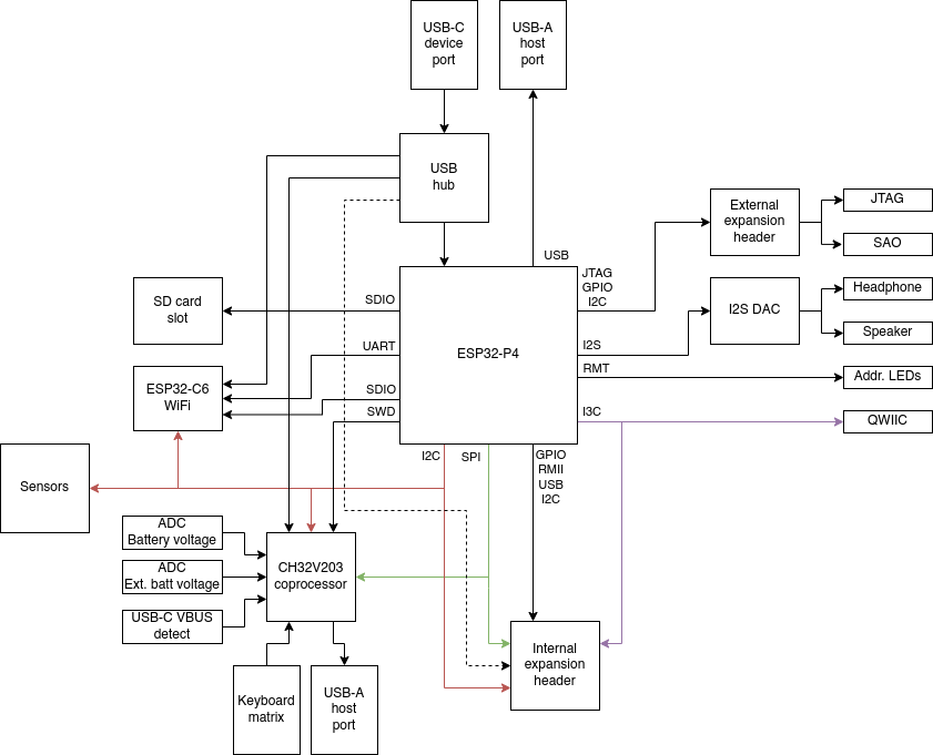

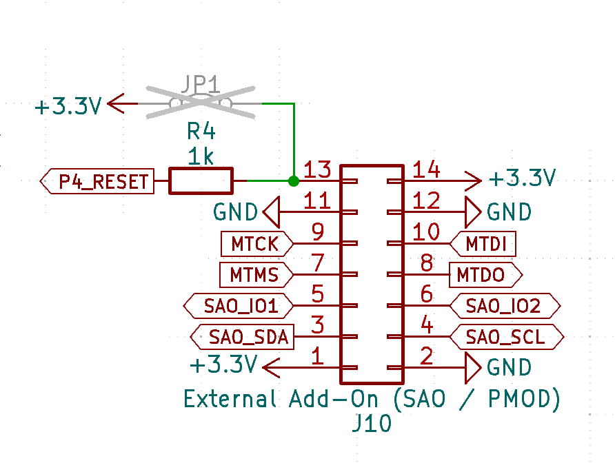


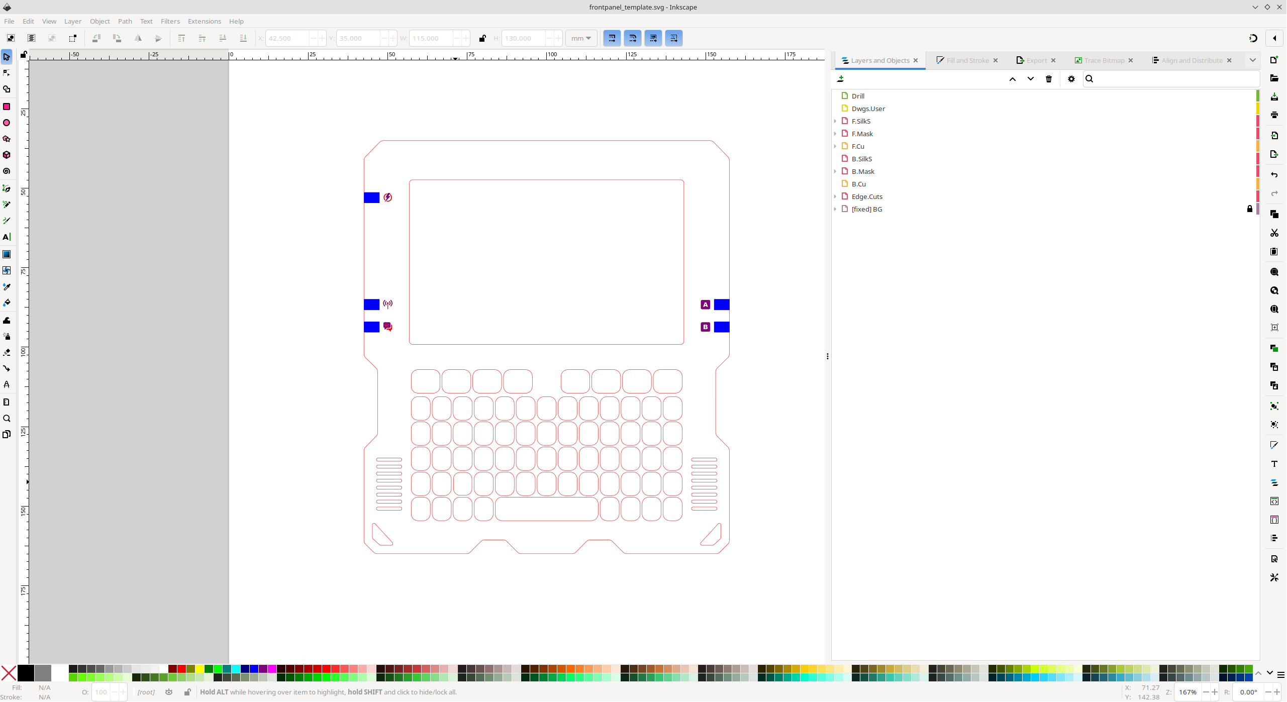


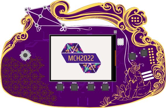
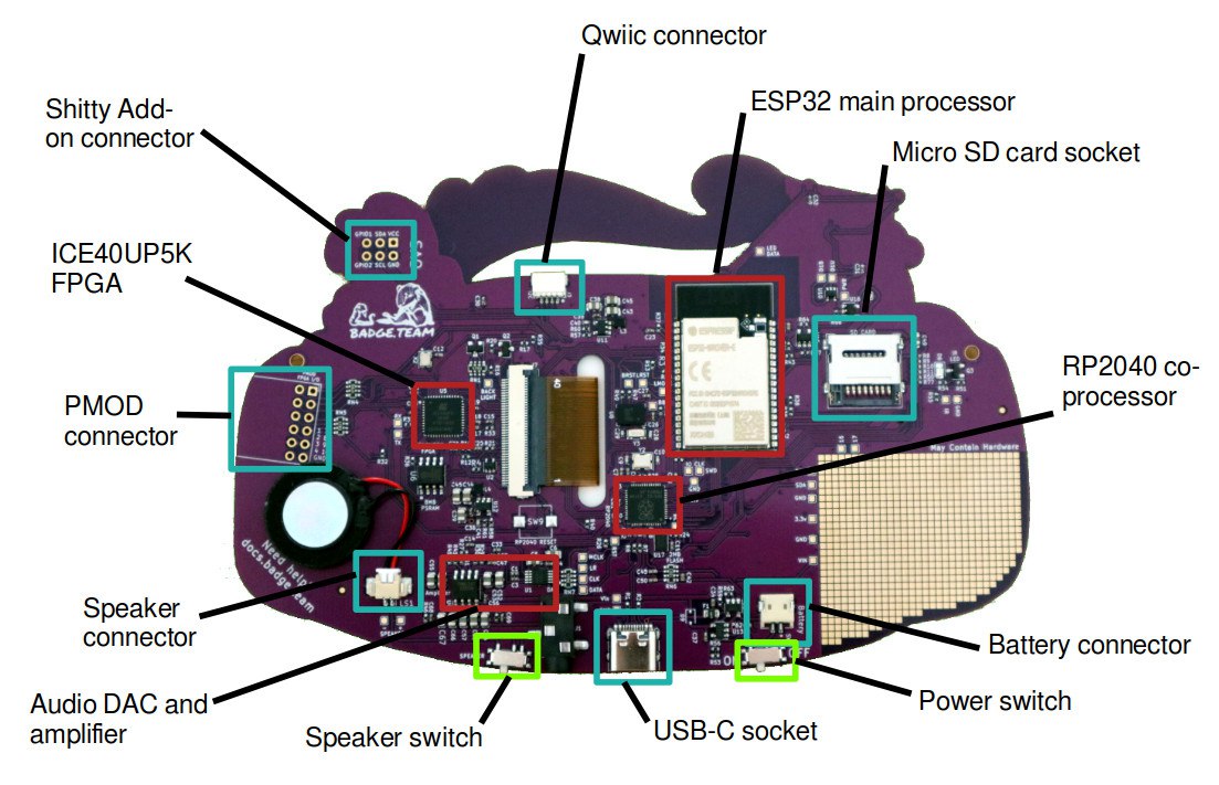


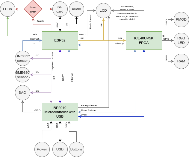
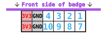
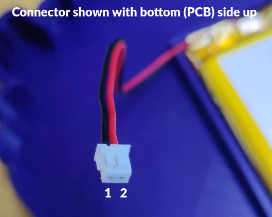
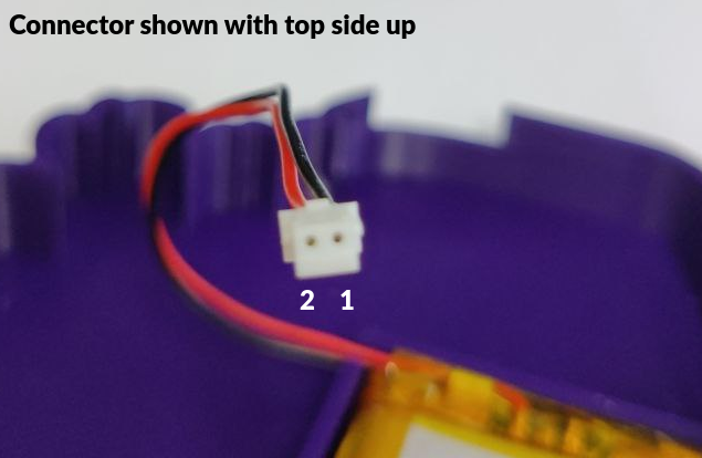
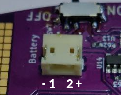
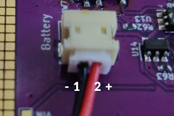
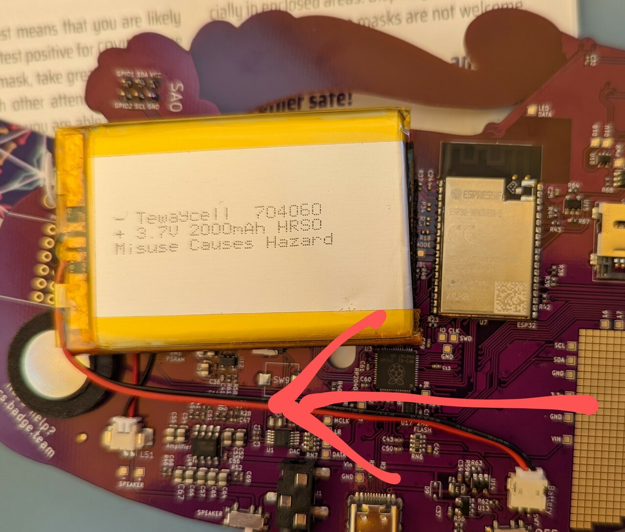
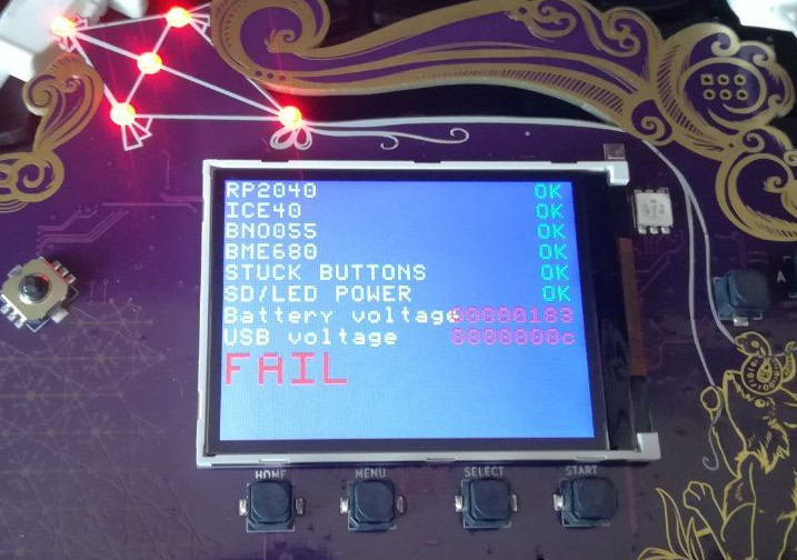
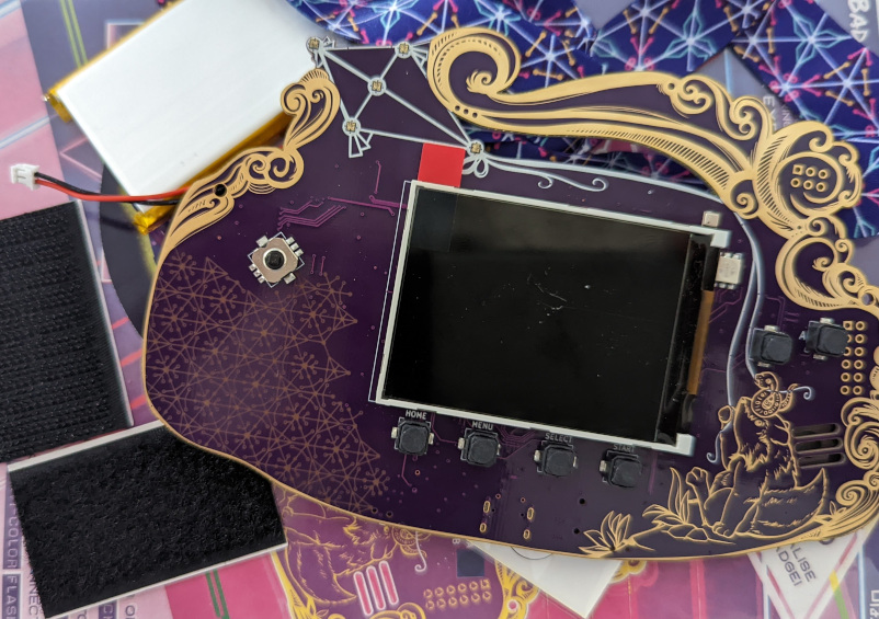
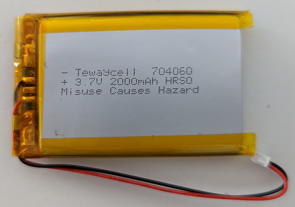
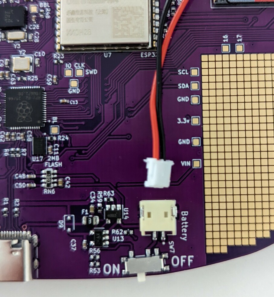
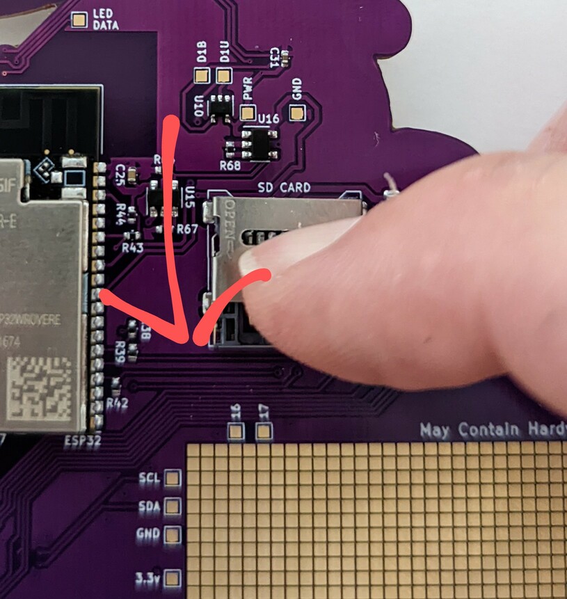
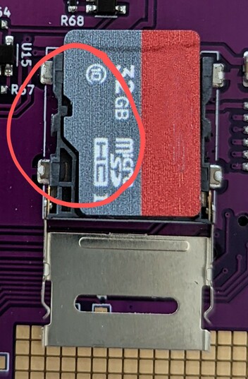
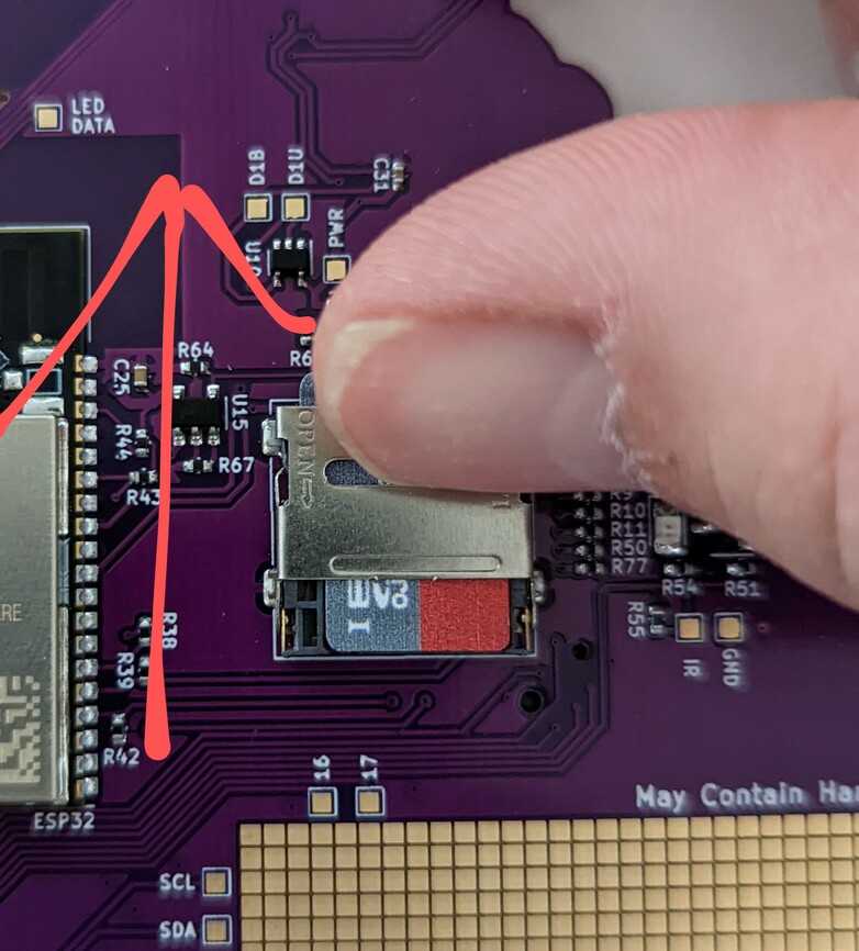
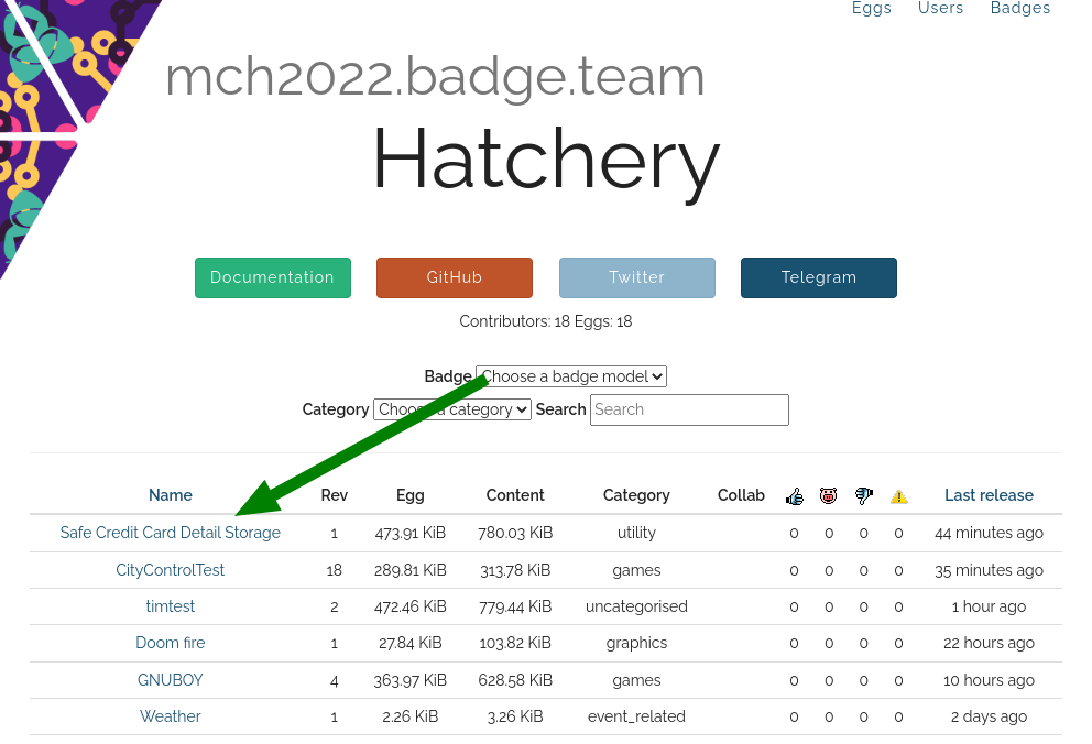
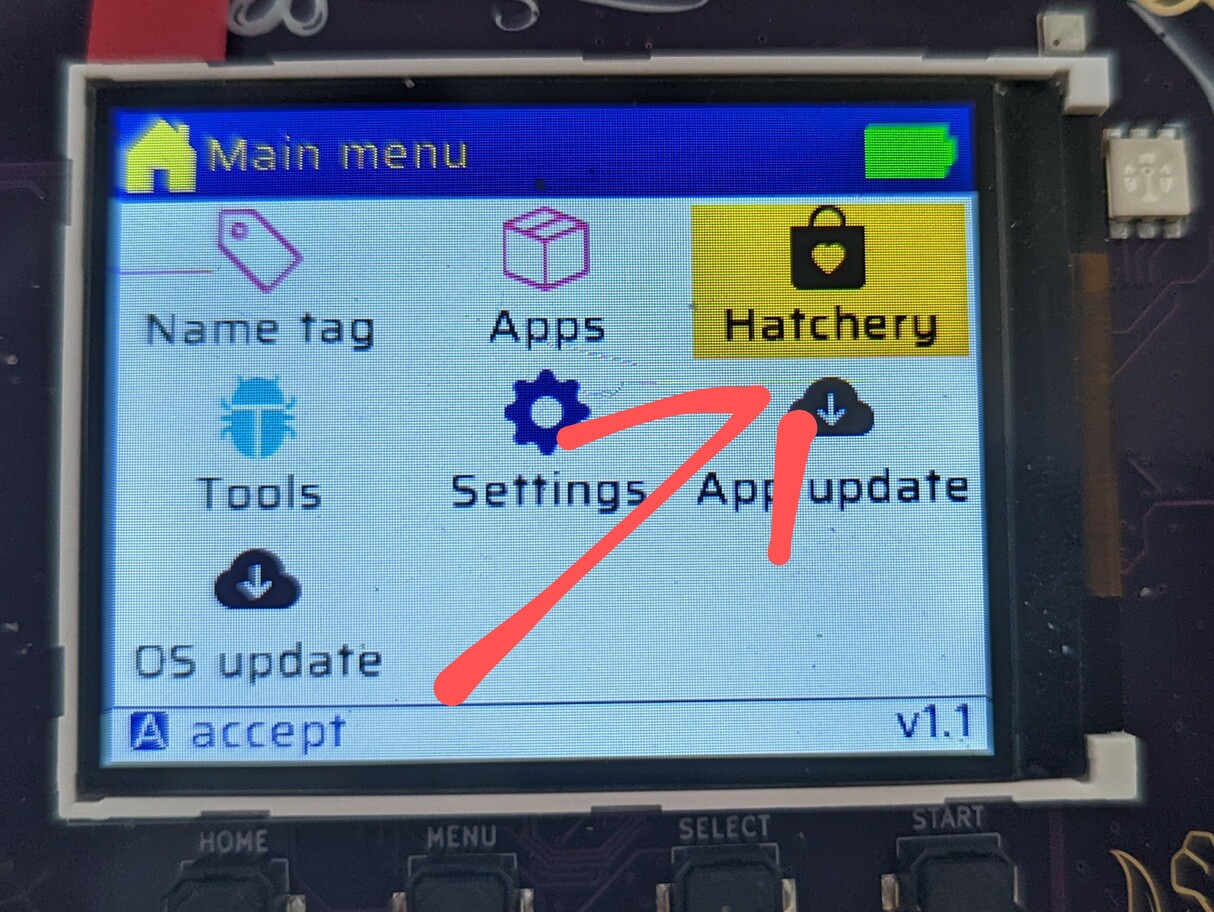
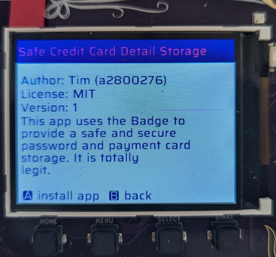
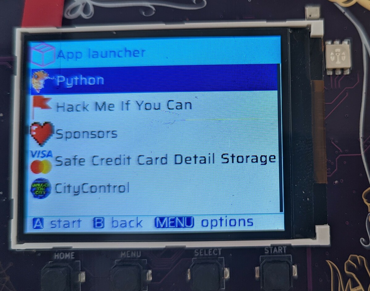
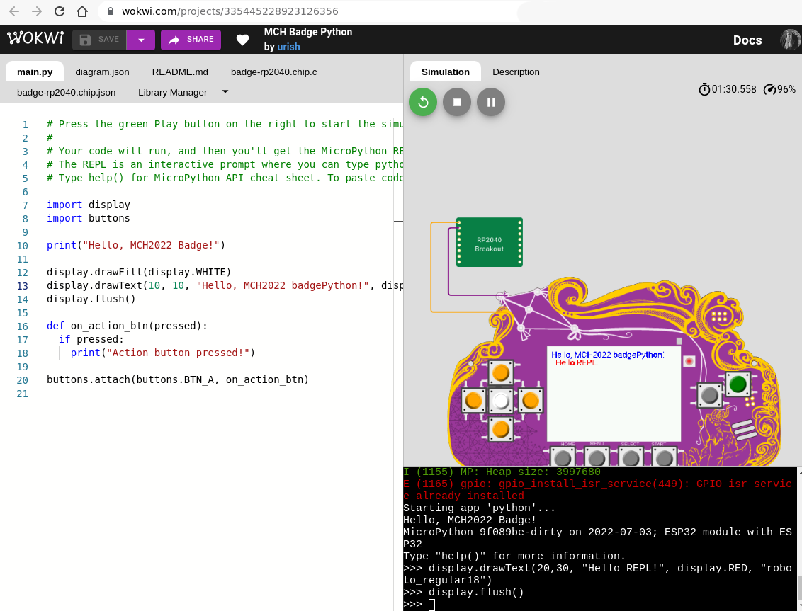


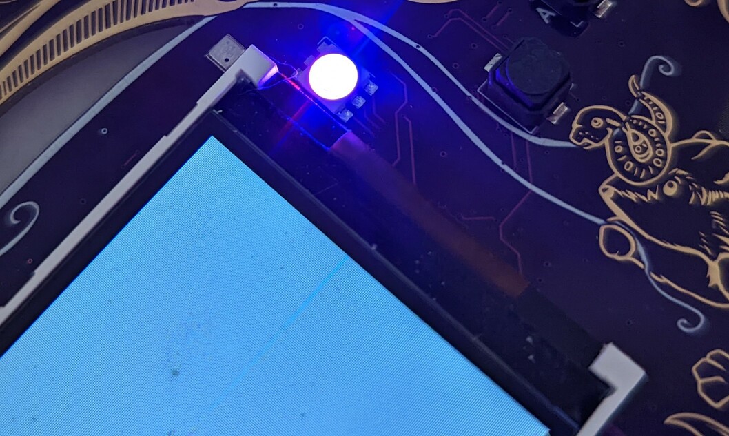


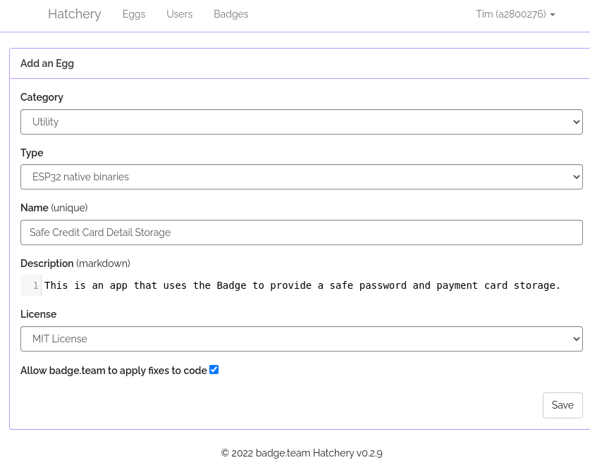
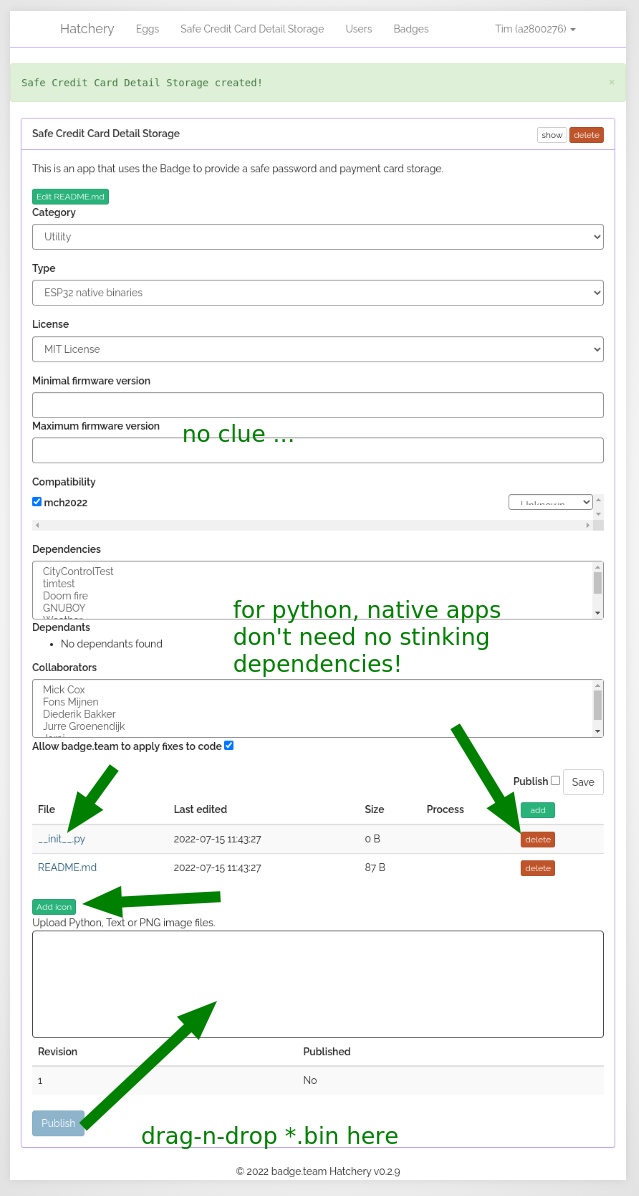
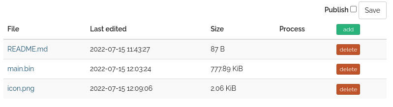
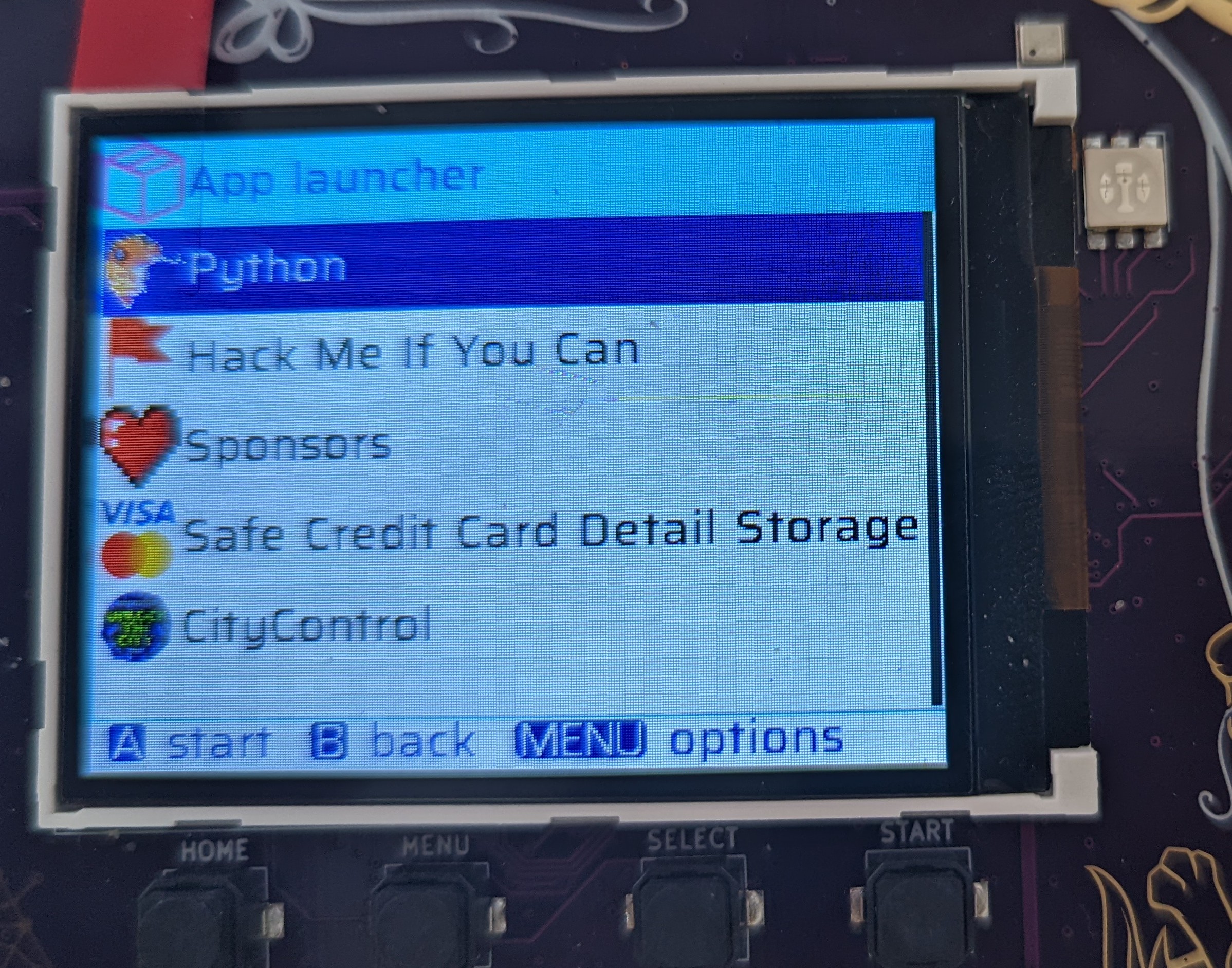


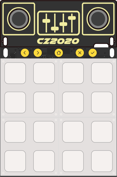
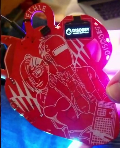
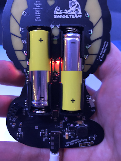
 Two red eyes and a red diamond an an unresponsive badge are the notification that the EEprom has been corrupted. Either you broke it, the code broke it, or it was another fault. No worries, visit a friendly Badge.team member and they can program that chip for you in under 15 seconds!