This is the multi-page printable view of this section. Click here to print.

Return to the regular view of this page.

Konsool badge

Introduction

The device will be the portable computer you wish you had in the 80s. Complete with on-device programming environment, a high resolution 60Hz screen and a full QWERTY keyboard this device is all the computing power you will need on a hand held hackable device!

The connectivity of this device is unparalleled, since the SHA badge WIFI and Bluetooth connectivity have been the norm, this badge adds long range low speed connectivity (LoRa) allowing for long range mesh networking! Who doesn’t want to talk to chat with friends over a kilometer away, no infrastructure needed!

Did we mention the dual core 400MHz Risc-V ESP32-P4 CPU?

Tanmatsu or Konsool?

The open-source badge design is released under the CERN-OHL-P license. This applies to both Konsool and Tanmatsu, which are essentially the same device.

  • Konsool is an open design, freely available for anyone to modify, extend, and use as they see fit.
  • Tanmatsu is the pre-assembled version sold by Nicolai Electronics, eliminating the hassle of sourcing components and manufacturing the PCB.

Selling electronic devices involves additional requirements, such as safety and environmental certifications. Badge.Team appreciates that Nicolai Electronics takes on these responsibilities, offering the badge practically at cost.

By providing both an open design and ready-to-use devices, we aim to foster a thriving ecosystem, ensuring ongoing support and updates for the community.

The Konsool hardware

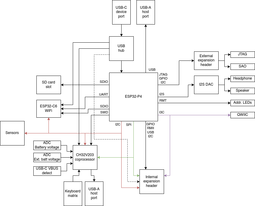
​The Konsool is powered by the ESP32-P4 which is a high-performance system-on-chip (SoC) from Espressif, featuring a dual-core RISC-V CPU running up to 400 MHz with AI instruction extensions. It integrates high-speed peripherals, including USB OTG 2.0 HS and Ethernet. The ESP32-P4 is tailored for applications requiring rich human-machine interfaces and power efficient computing. Making it (in our humble opinion) a good choice for a battery held device that humans interact with.

Additionally, an ESP32-C6 module provides WiFi, Bluetooth Low Energy, and IEEE802.15.4 wireless connectivity. This allows for internet access as well as compatibility with local mesh networks like Thread and ZigBee, ideal for developers and enthusiasts.

A LoRa radio module enables communication over LoRa networks, including long-range mesh services and classic (G)FSK modulation at either 433, 868 or 915MHz, depending on the module installed.

The device includes 16MB of built-in flash storage for firmware and applications, expandable via a micro SD card slot. This slot supports SD cards at both standard and high-speed (SDIO 3.0).

User interaction is provided through a QWERTY keyboard and a MIPI DSI display.

The expansion port enhance Konsool’s versatility by supporting expansion an board on the back of the the device. Exposing SPI, I2C, USB (2.0) and GPIO to the expansion board provides ample connectivity options for expansion board designs.

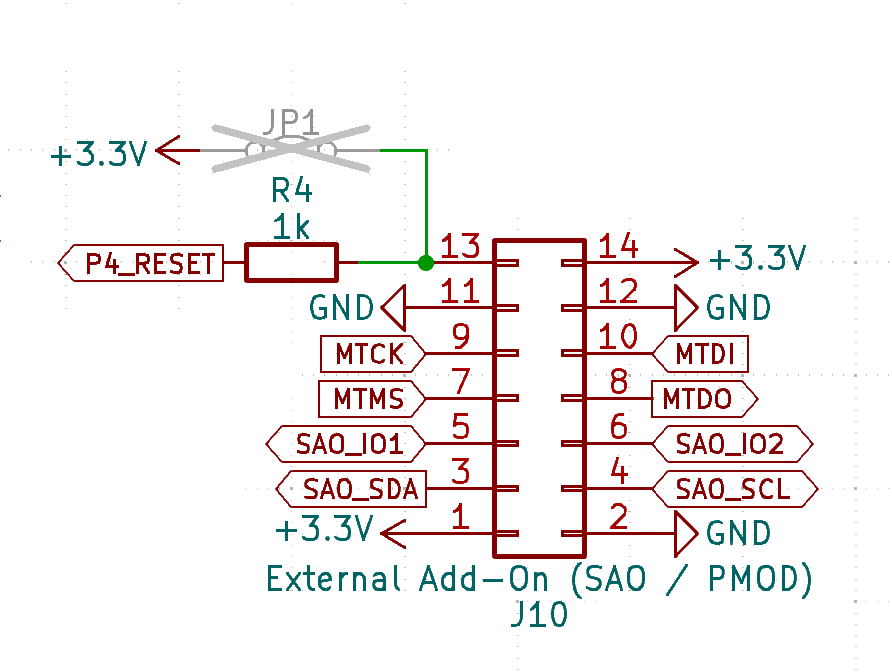
The side-facing CATT port provides connectivity to a JTAG debugger, and various PMOD and SAO-compatible accessories.

A QWIIC compatible connector allows the device to interface with numerous sensors from manufacturers like Sparkfun and Adafruit.

The ESP32-P4 also includes hardware-accelerated encoding of h264 video through its MIPI DSI and CSI interfaces. This powerful CPU can record video from devices such as a Raspberry Pi camera, encode it, and stream it wirelessly over WiFi.

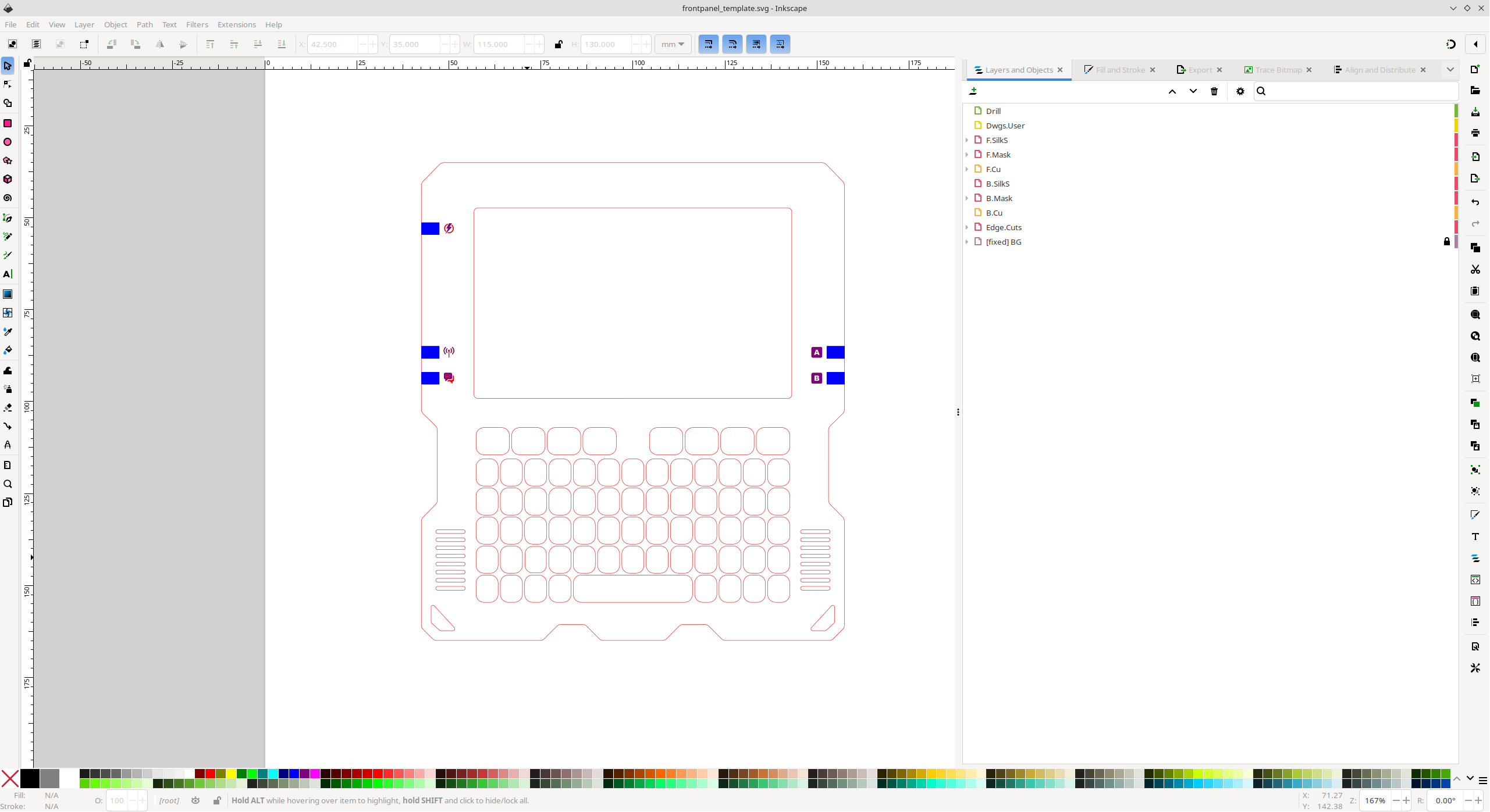
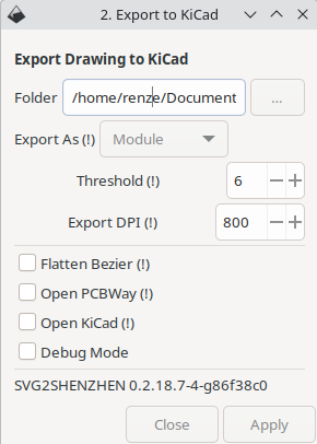
Custom front panels are feasible using the provided information, and 3D printable case designs are also available for those interested in additional customization. (A Case design in FreeCAD format coming soon)

The team

The Konsool would not have been possible without the help of our amazing volunteers.

NickNameRole
r3nz3Renze NicolaiHardware and Software development
RanzbakPaul HonigHardware, Testing and Documentation
JhaandJelle HaandrikmanTesting and review
RobotMan2412Julian ScheffersSoftware and Testing
AnkhanekoNikolettArtwork and more
Orange MurkerLunaSoftware and Testing
NightOwlNLEmiel BartDocumentation
NoorTesting
JayJay VisschedijkErgonomic board outline
WietsmanWietse BoonstraComponent footprints
KlimentKliment YanevReview hardware
AnusAnne Jan BrouwerSoftware

1 - Konsool quick start

Quick start

Peripherals

Navigation

Powering on the badge

Keep the power button pressed for ~2 seconds, until the power button turns red.

Powering off is done in the same manner.

Moving around in the launcher

  • Navigation is done using the arrow keys to navigate the menus.
  • An item can be activated by pressing the ’enter’ key.

Returning back to the launcher

Exiting an application back to the launcher should be done using: the red ‘X’ function button, which is located next to the escape.

When a program is started, basically a new firmware image is loaded into the ESP32-P4 so this will not work for all applications. Applications that behave well should support this though, and should return to the launcher.

Charging the badge

The badge is charged via the USB-C connector at the top left of the device. Note that the badge only charges the battery when turned on.

Since no handshake is done the amount of power a device is allowed to pull from the USB port is 0.5A, this means the battery at this time won’t charge quickly.

2 - Compatibility

2.1 - Camera

Software

Konsool applications can use the esp_cam_sensor driver to read frames from a MIPI CSI camera module.

The camera connector on Konsool has the same pinout as the 22 pin MIPI CSI connector found on the Raspberry Pi Zero and Raspberry Pi 5.

Supported sensors

SensorMax resolutionOutput format
GC21451600 x 1200RGB565
YCbCr422
8bit Raw RGB data
OV27101920 x 1080Raw RGB data
OV56452592 x 19448/10-bit Raw RGB data
RGB565
YUV/YCbCr422
YUV420
OV56472592 x 19448/10-bit Raw RGB data
SC035HGS640 x 480Raw MONO
Raw RGB data
SC202CS (SC2356)1600 x 12008/10-bit Raw RGB data
SC23361920 x 10808/10-bit Raw RGB data

3 - Konsool FAQ

Questions and Answers

4 - konsool hardware

4.1 - Konsool specifications

4.1.1 - Konsool battery

Battery

Specifications

labelValue
BrandTewaycell
TypeLithium ion
Voltage3.7V
Capacity2500 mAH (9.25Wh)

4.1.2 - Konsool ESP-C6

Specifications

labelValue
TypeESP32-C6-WROOM-1
ArchitectureRISC-V
Flash8 mb
WIFI version6
WIFI frequency2.4 GHz
BluetoothLE
IOTZigbee + THread (802.15.4)

Datasheet

For detailed specifications please look at the datasheet

4.1.3 - Konsool ESP-P4

#Specifications

labelValue
TypeESP32-P4
PSRAM16/32 mb
ArchitectureRISC-V
High speed cores2
High speed clock400MHz
Low speed cores1
Low speed clock40 MHz

For more details please look at the datasheet

4.1.4 - Konsool keyboard

#Specifications

QWERTY dome keyboard by Arturo

4.1.5 - Konsool screen

4.2 - Camera

Camera Compatibility List

CameraSensorConnectorLens“Night vision”FlashlightAutofocusTested
Camera Module for Raspberry Pi ZeroOV564722 pin Pi Zero/5 style120 degree fixedNoNoNoNo
Camera Module for Raspberry Pi ZeroOV564722 pin Pi Zero/5 style72 degree fixedYesNoNoNo
Camera Module for Raspberry Pi ZeroOV564722 pin Pi Zero/5 style72 degree fixedNoNoNoNo
Camera Module for Raspberry Pi ZeroOV564722 pin Pi Zero/5 style160 degree fixedNoNoNoNo
Camera Module for Raspberry Pi ZeroOV564722 pin Pi Zero/5 style120 degree fixed (big lens)NoNoNoNo
Camera Module for Raspberry Pi ZeroOV564722 pin Pi Zero/5 style120 degree motorizedNoNoYesNo
Camera Module for Raspberry Pi ZeroOV564722 pin Pi Zero/5 style72 degree motorizedNoNoYesNo
Raspberry Pi 5 cameraOV5647Comes with cable to 22 pin Pi Zero/5 styleFF 69NoNoNoNo
Raspberry Pi 5 cameraIMX519Comes with cable to 22 pin Pi Zero/5 styleUnknownNoNoYesNo
Raspberry Pi 5 cameraOV5647Comes with cable to 22 pin Pi Zero/5 styleAF 65"NoNoYesNo
Raspberry Pi 5 cameraOV5647Comes with cable to 22 pin Pi Zero/5 styleIR-CUT 175 2YesIRNoNo
Raspberry Pi 5 cameraOV5647Comes with cable to 22 pin Pi Zero/5 styleIR-CUT 175YesNoNoNo
Raspberry Pi 5 cameraOV5647Comes with cable to 22 pin Pi Zero/5 styleIR-CUT 75 2"YesIRNoNo
Raspberry Pi 5 cameraOV5647Comes with cable to 22 pin Pi Zero/5 styleIR-CUT 75YesNoNoNo
Raspberry Pi 5 cameraOV5647Comes with cable to 22 pin Pi Zero/5 styleMF 220NoNoNoNo
Raspberry Pi 5 cameraOV5647Comes with cable to 22 pin Pi Zero/5 styleMF 175NoNoNoNo
Raspberry Pi 5 cameraOV5647Comes with cable to 22 pin Pi Zero/5 styleMF 130 Night 2YesIRNoNo

4.3 - Konsool connectors

Diagram

Blockdiagram

4.4 - Konsool pinouts

In this section you can find the pinout of the chips and connectors of the device.

4.4.1 - Konsool connectors

4.4.1.1 - CATT pinout

Description

The CATT connector combines several different connectors in one.

  • Special Addon (SAO)
  • JTAG
  • PMOD

Because of this multi functional nature, the name for the connector is CATT (Connect all the things), even though there are more kind of things to connect.

SAO

CATT pinout
  • *DET: Detect, when pulled down during power up, JTAG functionality is provided
  • *3V3: Not connected by default, jumper on the PCB needs to be closed to supply 3V3

Schematic

CATT schematic

4.4.1.2 - Internal expansion port

Back Expansion layout

Back Expansion pinout

Back expansion port

This port is not exposed by default, and a modified back cover needs to be used to make it accessible. For this reason the port is also named the “internal expansion port”.

FunctionNameGPIODescriptionNotes
Power outputVOTG-Output from booster DC/DC converter in the PMIC5 volt when booster is enabled, +/- VSYS when booster is disabled
USBHUB_USB1_P-Port on USB hub for USB-C port (DP)Can be used to expose an USB device on the add-on to the PC plugged into the USB-C port
Power outputHUB_USB1_N-Port on USB hub for USB-C port (DN)Can be used to expose an USB device on the add-on to the PC plugged into the USB-C port
USBVBATT-Battery voltage (3.0 – 4.2v)Directly connected to battery connector, always on even when the device is turned off
Power outputVSYS-System voltage (3.0 – 5.0v)Switched power rail for powering the system, can be powered by battery or USB-C port, off when device is turned off
Power ref.GND-Voltage reference (ground)
Power output+3.3v-Main logic supply rail (3.3v)
I2CINT_SCLInternal I2C bus, shared with other I2C devices (SCL)Used to connect I2C devices and an EEPROM for add-on identification
I2CINT_SDAInternal I2C bus, shared with other I2C devices (SDA)Used to connect I2C devices and an EEPROM for add-on identification
GPIOE036GPIO
GPIOE10GPIO
GPIOE26GPIO, also connected to camera GPIO 1Shared with camera connector
GPIOE346GPIO, VSDCARD LDO must be enabled to use this pinConnected via level shifter, externally these GPIOs operate at 3.3v but the GPIOs are powered by the VSDCARD power domain
GPIOE447GPIO, VSDCARD LDO must be enabled to use this pinConnected via level shifter, externally these GPIOs operate at 3.3v but the GPIOs are powered by the VSDCARD power domain
GPIOE548GPIO, VSDCARD LDO must be enabled to use this pinConnected via level shifter, externally these GPIOs operate at 3.3v but the GPIOs are powered by the VSDCARD power domain
GPIOE645GPIO, VSDCARD LDO must be enabled to use this pinConnected via level shifter, externally these GPIOs operate at 3.3v but the GPIOs are powered by the VSDCARD power domain
GPIOE77GPIO, in low power domain of P4, has 51k pull-up resistorCan be used as wakeup pin to wake up the ESP32-P4 from deep sleep
GPIOE854GPIO
GPIOE949GPIO
GPIOE1053GPIO
GPIOEXT_USB_P26Can be used as GPIO or as USB FS PHY (DP)The USB PHYs of the P4 can be swapped between the USB serial/jtag and user controlled USB peripheral. If badgelink is used then this PHY exposes the serial/jtag peripheral
GPIOE1152GPIO
GPIOEXT_USB_N27Can be used as GPIO or as USB FS PHY (DN)The USB PHYs of the P4 can be swapped between the USB serial/jtag and user controlled USB peripheral. If badgelink is used then this PHY exposes the serial/jtag peripheral
GPIOE1251GPIO
GPIOP4_TX37Exposes boot console of P4, can be used as GPIOMust be low during boot
GPIOE1350GPIO
GPIOP4_RX38Exposes boot console of P4, can be used as GPIOMust be high during boot
I2SI2S_MCLKDigital audio bus master clockReference clock for connected I2S devices
I2SI2S_LRCKDigital audio bus word clockWord clock (left-right selection) for connected I2S devices
I2SI2S_DATADigital audio bus data outputData output from mainboard for connected I2S DACs
I2SI2S_SCLKDigital audio bus sample clockSample clock for connected I2S devices
Power output+3.3v-Main logic supply rail (3.3v)
I3CI3C_SDAI3C bus, shared with QWIIC connector (SDA)Can also be used as I2C bus
Power ref.GND-Voltage reference (ground)
I3CI3C_SCLI3C bus, shared with QWIIC connector (SCL)Can also be used as I2C bus

Limitations & warnings

  • Total for all 3.3v outputs must not exceed 1A of current. It is generally adviced to stay well below this figure.
  • Do not exceed a current of 1.5A from the battery when the battery is connected to the internal battery connector
  • Do not charge the battery via the internal add-on port

4.4.2 - IC pinouts

IC pinout mapping to functions on the board.

4.4.2.1 - CH32V203 pinout

CH32V203

Pin NumberPin NameNet NameDirectionNotes
1VBATVBATPowerRegulated 2.5V supply
2PC13POWER_ON_PULSEOutputEmit pulse to wake up badge
3PC14XTALInputCrystal Oscillator
4PC15XTALInputCrystal Oscillator
5PD0AMP_ENOutputEnable audio speaker amplifier
6PD1USB_ENABLEOutputEnable to USB-A OTG port
7NRSTNRSTInput3V3
8VSSAVSSAPowerAnalog Ground
9VDDAVDDAPowerAnalog Power
10PA0INTOutputInterrupt line to ESP32-P4
11PA1KB_ROW5OutputKeyboard IO
12PA2KB_ROW8OutputKeyboard IO
13PA3KB_ROW4OutputKeyboard IO
14PA4KB_ROW3OutputKeyboard IO
15PA5KB_ROW7OutputKeyboard IO
16PA6KB_ROW6OutputKeyboard IO
17PA7KB_COL3InputKeyboard IO
18PB0KB_COL7InputKeyboard IO
19PB1KB_COL2InputKeyboard IO
20PB2/BOOT1KB_COL6InputKeyboard IO
21PB10PM_SCLOutputI2C Clock PMIC (Power controller)
22PB11PM_SDABidirectionalI2C Data PMIC
23VSS1GNDPowerGround
24VDDIO1+3.3VPowerPower Supply
25PB12KB_COL1InputKeyboard IO
26PB13KB_COL5InputKeyboard IO
27PB14KB_COL0InputKeyboard IO
28PB15KB_COL4InputKeyboard IO
29PA8KB_ROW0OutputKeyboard IO
30PA9KB_ROW1OutputKeyboard IO
31PA10KB_ROW2OutputKeyboard IO
32PA11LED_DATAOutputSerial data to SK6805 LEDs
33PA12POWER_BTNInputPower button input (low when pressed)
34PA13SWDIOBidirectionalDebug Interface CH32V203
35VSS2GNDPowerGround
36VDD2+3.3VPowerPower Supply
37PA14SWCLKOutputDebug Clock
38PA15SD_DETInputSD card detect
39PB3KEYBOARD_BLOutputEnable backlight Keyboard
40PB4DISPLAY_BLOutputEnable backlight display
41PB5HP_DETInputHead phone detect
42PB6SCLinputI2C Clock shared bus
43PB7SDABidirectionalI2C Data shared bus
44BOOT0DCAM_IO0OutputCamera module power enable (if present)
45PB8RADIO_ENABLE / CAM_IO0OutputEnable C6 and MIPI_CSI camera IO 0
46PB9PM_INTInputInterrupt signal PMIC
47VSS3GNDPowerGND
48VDDIO3+3.3VPowerPower

4.4.2.2 - ESP32C6 pinout

Schematic

ESP32 Pin table

PinNameNetDirectionFunction
1GNDPower
23V3Power
3ENENInputEnable signal from the CH32V203
4IO4LORA_DIO1InputLoRa IRQ (Interrupt)
5IO5LORA_BUSYInputLoRa Busy Signal
6IO6I2C_SDABidirectionalI2C Data Line
7IO7I2C_SCLInputI2C Clock Line
8IO0LORA_SCKInputLoRa SPI Clock
9IO1LORA_CSOutputLoRa SPI Chip Select
10IO8INTOutputInterrupt line to ESP32-P4
11IO10LORA_RESETOutputLoRa Reset
12GNDPower
13IO12C6_USB1_NBidirectionalVia USB hub to USB-C port
14IO13C6_USB1_PBidirectionalVia USB hub to USB-C port
15IO9BOOTInputBOOT mode select and VUSB (USB-A power) enable line
16IO18SDIO_CMDBidirectionalSDIO bus to P4 Command
17IO19SDIO_CLKOutputSDIO bus to P4 Clock
18IO20SDIO_DATA0BidirectionalSDIO bus to P4 Data Line 0
19IO21SDIO_DATA1BidirectionalSDIO bus to P4 Data Line 1
20IO22SDIO_DATA2BidirectionalSDIO bus to P4 Data Line 2
21IO23SDIO_DATA3BidirectionalSDIO bus to P4 Data Line 3
22NC
23IO15IR_LEDOutputInfrared LED Control
24RXD0RXInputUART to P4 Receive
25TXD0TXOutputUART to P4 Transmit
26IO3LORA_MISOInputLoRa SPI MISO
27IO2LORA_MOSIOutputLoRa SPI MOSI
28GNDPower
29GNDPower

4.4.2.3 - ESP32-P4 pinout

ESP32-P4 (U8)

LDO

Pin numberPin namePin net
71VFB/VO1VFLASH
72VFB/VO2VPSRAM
73VFB/VO3VMIPI
74VFB/VO4VSDCARD

GPIO

GPIODirection / BusFunctionNote
0User controlledInternal Add-On: E2
1InputInterrupt from CH32V203 coprocessorHigh on interrupt from CH32 co-processor
2User controlledJTAG: MTCK, PMOD: IOCan be used as JTAG interface or as generic GPIO on the external Add-On connector
3User controlledJTAG: MTDI, PMOD: IOCan be used as JTAG interface or as generic GPIO on the external Add-On connector
4User controlledJTAG: MTMS, PMOD: IOCan be used as JTAG interface or as generic GPIO on the external Add-On connector
5User controlledJTAG: MTDO, PMOD: IOCan be used as JTAG interface or as generic GPIO on the external Add-On connector
6InputE1 expansion + Camera module LED enableRead from the coprocessor I2C device to clear the interrupt condition
7Input / User controlledInterrupt from internal Add-On boardCan also be used as GPIO, depending on the needs of the internal Add-On board
8InputInterrupt from ESP32-C6 radioControlled by ESP-HOSTED component
9I2C bus SDAInternal I2C bus dataInternal I2C bus connecting the ESP32-P4 to the ESP32-C6, CH32V203 coprocessor, Bosch sensors and internal Add-On board
10I2C bus SCLInternal I2C bus clockInternal I2C bus connecting the ESP32-P4 to the ESP32-C6, CH32V203 coprocessor, Bosch sensors and internal Add-On board
11InputLCD TE (Tearing effect)Synchronization pin for frame sync, used to avoid tearing
12User controlledSAO: I2C SDA, PMOD: IOCan be used as I2C interface for SAO Add-On boards or as generic GPIO on the external Add-On connector
13User controlledSAO: I2C SCL, PMOD: IOCan be used as I2C interface for SAO Add-On boards or as generic GPIO on the external Add-On connector
14OutputLCD resetHardware reset for the LCD controller
15User controlledSAO: IO1, PMOD: IOCan be used as generic GPIO for SAO Add-On boards or as generic GPIO on the external Add-On connector
16SDIO 2.0SDIO bus for ESP32-C6: CMDControlled by ESP-HOSTED component
17SDIO 2.0SDIO bus for ESP32-C6: CLKControlled by ESP-HOSTED component
18SDIO 2.0SDIO bus for ESP32-C6: D0Controlled by ESP-HOSTED component
19SDIO 2.0SDIO bus for ESP32-C6: D1Controlled by ESP-HOSTED component
20SDIO 2.0SDIO bus for ESP32-C6: D2Controlled by ESP-HOSTED component
21SDIO 2.0SDIO bus for ESP32-C6: D3Controlled by ESP-HOSTED component
22BidirectionalCH32V203 programming interface: SWDIOFor coprocessor firmware updates
23OutputCH32V203 programming interface: SWCLKFor coprocessor firmware updates
24USBUSB DN, port 1 on USB hub (USB-C port)
25USBUSB DP, port 1 on USB hub (USB-C port)
26User controlledInternal Add-On: USB DN or generic GPIOPin 24
27User controlledInternal Add-On: USB DP or generic GPIOPin 22
28I2SI2S: dataInternal I2S to the DAC towards headphone jack and speaker
29I2SI2S: sample clockInternal I2S to the DAC towards headphone jack and speaker
30I2SI2S: master clockInternal I2S to the DAC towards headphone jack and speaker
31I2SI2S: lr clockInternal I2S to the DAC towards headphone jack and speaker
32I3CI2C/I3C QWIIC port: SCLConnected to external I3C connector
33I3CI2C/I3C QWIIC port: SDAConnected to external I3C connector
34User controlledSAO: IO2, PMOD: IO
35User controlledInternal Add-On: E1 / BOOT1 during reset release SPI boot, 0 is DEBUG (page 32 data sheet) (Connected up to volume down button)
36User controlledInternal Add-On: E0Depending on fuses can influence boot
37Output / User controlledDebug UART transmitPin 26 on the back expansion
38Input / User controlledDebug UART receivePin 28 on the back expansion
39SDIO 3.0SD card slot: D0
40SDIO 3.0SD card slot: D1
41SDIO 3.0SD card slot: D2
42SDIO 3.0SD card slot: D3
43SDIO 3.0SD card slot: CLK
44SDIO 3.0SD card slot: CMD
45User controlledInternal Add-On: E6Pin 17 Back expansion header
46User controlledInternal Add-On: E3Pin 14 Back expansion header
47User controlledInternal Add-On: E4Pin 15 Back expansion header
48User controlledInternal Add-On: E5Pin 16 Back expansion header
49User controlledInternal Add-On: E7Pin 20 Back expansion header
50User controlledInternal Add-On: E8Pin 27 Back expansion header
51User controlledInternal Add-On: E9Pin 25 Back expansion header
52User controlledInternal Add-On: E10Pin 23 Back expansion header
53User controlledInternal Add-On: E11Pin 21 Back expansion header
54User controlledInternal Add-On: E12Pin 19 Back expansion header

4.5 - Frontpanel

This page describes how to design and order a Konsool badge frontpanel.

Designing a frontpanel using Inkscape, svg2shenzhen and KiCad

The first step of designing a frontpanel is creating artwork that can be converted into a KiCad footprint. For this Inkscape and the Inkscape plugin svg2shenzhen are used.

Of course it is also possible to use any other method which allows you to import a footprint into KiCad so if you’re using a different method then you can skip ahead to the KiCad section.

Instructions on how to install svg2shenzhen can be found in the readme of the repository.

Inkscape

After opening the design file in Inkscape you will notice that multiple layers are used. Each of the layers in the design corresponds with a KiCad layer, this allows you to define how a shape should appear on the circuit board.

The most important layers are:

  • Edge.Cuts: this is the outline of the board, the PCB manufacturer will use a CNC mill to cut the board following the edges of the object on this layer.
  • F.Cu and B.Cu: these layers define where to place copper on the front and back of the circuit board.
  • F.Mask and B.Mask: all shapes drawn on this layer are cut out of the colored soldermask layer of the board.
  • F.SilkS and B.SilkS: these layers are printed on the front and back silkscreen layer respectively. The silkscreen layer is a non-conductive layer of ink usually used to add reference designators and text to a circuit board.

Export the design to KiCad by navigating to Extensions > Svg2Shenzhen > 2. Export to Kicad...

Svg2Shenzhen export dialog

KiCad

4.5.1 - Konsool artwork

5 - Konsool software

(work in progress, please check this page again later)

5.1 - Konsool apps

5.1.1 - Konsool local apps

5.1.2 - Software Hub for Konsool

#Uploading, Downloading, Creating, Contributing

5.1.2.1 - Creating apps

5.1.2.2 - Downloading Apps

5.1.2.3 - Uploading apps

5.2 - Konsool settings

5.2.1 - Konsool LoRa

#Meshtastic (work in progress, please check this page again later)

5.2.2 - Konsool Software Hub settings

(work in progress, please check this page again later)

5.2.3 - Konsool wifi

(work in progress, please check this page again later)

5.3 - Konsool updating

(work in progress, please check this page again later)

5.3.1 - Konsool apps

(work in progress, please check this page again later)

5.3.2 - Konsool firmware

(work in progress, please check this page again later)

6 - Konsool expansion boards

6.1 - 18650 extension

18650 Extension

Introduction

Simple extension that attaches to the extension port at the back, and contains 2 18650 cells. This extends the battery time for the Konsool / Tanmatsu badge with several hours.

The extension features protection IC’s for both cells individually, to minimize risks related to the lithium batteries.

Features

  • Protection IC per 18650 CELL
  • On/Off switch
  • Charges off the USB-C power from the Konsool/Tanmatsu
  • M2 mounting holes to fasten the battery holder securely

Project

The project can be found here on Github.

Maturity

A prototype run has been done, and the hardware has been tested on a Tanmatsu V4 prototype (See pictures below).

Real life pictures

6.2 - Zero expansion boards

Zero expansion board

Introduction

The Konsool has al lot of capabilities already in a pretty handy form factor. To take advantage of the keyboard, powerful CPU to for example play with technologies like NFC, RFID and sub GHz radio extra circuitry is required. Even though this idea is not my own (thanks Renze) I do feel motivated to make this board given my interest in lock picking sports.

Disclaimer

It is important that this device is used for educational purposes only, the only locks that should be opened are either your own or with express permission of the owner of said lock.

The goal of this device is to improve security and educate, not do enable illegal activities.

I the designer do not take any responsibility for the how this device is used, if you manage to get into trouble using this device the responsibility is your own.

Planned Features

  • 100 - 150 kHz RFID tag reading and writing
  • Sub GHz radio capabilities using CC1101
  • RFID receiver (The Konsool board has the transmitter LED on the PCB)
  • IButton

Project

Main project

Intermediate

Most circuitry on the expansion is based on the Flipper zero schematics, as they are published on their website.

For the RFID circuitry this was not enough for me to understand the OpAMP circuits, here the creating RFID reader from scratch helped understanding the design.

Maturity

As for 2025-03-22:

This project in it’s early stages of development where major milestones still need to be reached.

Milestones:

  • Create RFID prototype board
    • Troubleshoot RFID analog circuit make stable
    • Create proof of concept to read RFID tag
    • Create proof of concept to write RFID tag
  • Choose type of microcontroller (STM32 / CH32)
  • Choose antenna type PCB coil vs wire coil
  • Integrate RFID prototype into expansion
  • Create sub 1GHz radio module prototype board
    • Troubleshoot design to get a stable circuit
    • Create a proof of concept sending data
    • Create a proof of concept receiving data
  • Create Konsool prototype board for development (Some work done)
  • Create firmware for the MCU on the extension board
  • Create software on the Konsool

At the moment of writing work needs to be done stabilizing the RFID analog circuitry.

  • The RC circuit introduces DC offset, that prevents the carrier circuit from working correctly
  • The Oscillator circuit is unstable an has a low frequency wobble
  • The output does show a consistent bit stream when a RFID card is presented to the coil.

Findings:

  • The schematic circuitry uses envelope detector circuits to decode the RFID signal.
  • The idea of prototyping on a breadboard is not going to work as the cross talk of signals on a breadboard is too big which drowns out the RFID signals.

Contributors

NickNameRole
RanzbakPaul HonigPCB design / test software

Work in progress pictures