ESP32C6 pinout
Schematic
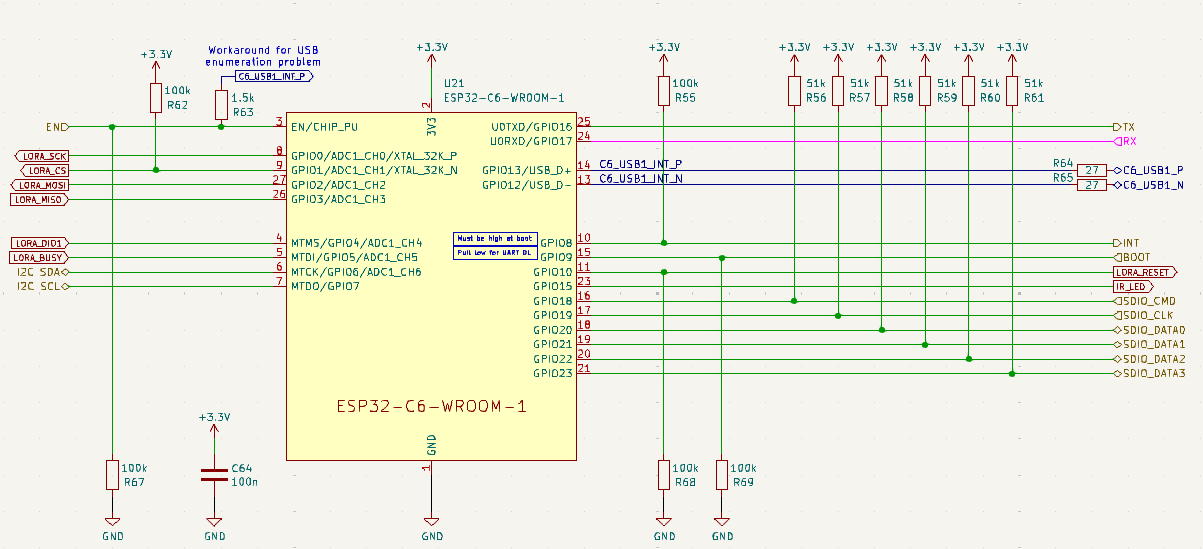
ESP32 Pin table
| Pin | Name | Net | Direction | Function |
|---|
| 1 | GND | Power | | |
| 2 | 3V3 | Power | | |
| 3 | EN | EN | Input | Enable signal from the CH32V203 |
| 4 | IO4 | LORA_DIO1 | Input | LoRa IRQ (Interrupt) |
| 5 | IO5 | LORA_BUSY | Input | LoRa Busy Signal |
| 6 | IO6 | I2C_SDA | Bidirectional | I2C Data Line |
| 7 | IO7 | I2C_SCL | Input | I2C Clock Line |
| 8 | IO0 | LORA_SCK | Input | LoRa SPI Clock |
| 9 | IO1 | LORA_CS | Output | LoRa SPI Chip Select |
| 10 | IO8 | INT | Output | Interrupt line to ESP32-P4 |
| 11 | IO10 | LORA_RESET | Output | LoRa Reset |
| 12 | GND | Power | | |
| 13 | IO12 | C6_USB1_N | Bidirectional | Via USB hub to USB-C port |
| 14 | IO13 | C6_USB1_P | Bidirectional | Via USB hub to USB-C port |
| 15 | IO9 | BOOT | Input | BOOT mode select and VUSB (USB-A power) enable line |
| 16 | IO18 | SDIO_CMD | Bidirectional | SDIO bus to P4 Command |
| 17 | IO19 | SDIO_CLK | Output | SDIO bus to P4 Clock |
| 18 | IO20 | SDIO_DATA0 | Bidirectional | SDIO bus to P4 Data Line 0 |
| 19 | IO21 | SDIO_DATA1 | Bidirectional | SDIO bus to P4 Data Line 1 |
| 20 | IO22 | SDIO_DATA2 | Bidirectional | SDIO bus to P4 Data Line 2 |
| 21 | IO23 | SDIO_DATA3 | Bidirectional | SDIO bus to P4 Data Line 3 |
| 22 | NC | | | |
| 23 | IO15 | IR_LED | Output | Infrared LED Control |
| 24 | RXD0 | RX | Input | UART to P4 Receive |
| 25 | TXD0 | TX | Output | UART to P4 Transmit |
| 26 | IO3 | LORA_MISO | Input | LoRa SPI MISO |
| 27 | IO2 | LORA_MOSI | Output | LoRa SPI MOSI |
| 28 | GND | Power | | |
| 29 | GND | Power | | |