MCH2022 badge

The MCH2022 badge is our most advanced badge yet. Shaped like a game console
this badge is a powerhouse filled with cool technology.
Once assembled, you can use the badge to display your name, write Python
code and maybe play a game or find an Easter Egg, but don’t forget: the
real fun starts when you hack it to make it your own!

Getting Started
We’ve assembled some resources to quickly get
started.
Getting Help (and helping …)
Reread the instructions if something isn’t working. Then go to our
Troubleshooting Guide
Check out these resources if you run into trouble.
Case and frontpanel
You can find a 3D printable case and a lasercuttable frontpanel in this GIT repository.
The Hardware
The badge contains an Espressif ESP32 Wrover-e WiFi module with 16MB of
flash storage and 8MB of PSRAM, an Raspberry Pi RP2040 microcontroller
chip for advanced USB communication and board management and a Lattice
ICE40UP5K FPGA for hardware accelerated graphics.
It also contains a bunch of stuff (TODO elaborate “stuff”).
The hardware is described in more detail in the hardware section.
The Software
The ESP32 loads an application chooser menu when you first power it on.
Once loaded, you can launch a number of preinstalled applications:
- the Name-Tag app
- a Micropython scripting environment
- a sensor playground for the Bosch sensors
- The Hatchery where you can load more apps!
and the app contains a link to the Hatchery an app store you can use to
load more apps. And more importantly, where you can publish app you
write yourself.
The software is still in active development, more information will be
published here soon.


- ALLNET China was our production partner, for which we are more than grateful. They took care of sourcing most components and oversaw the production process in China, saving us a lot of work and potential headaches and allowing us to focus on the product!
- Espressif was very generous to donate us all of the ESP32-WROVER-E modules we needed. The ESP32 has proven itself to be a solid basis for badges in the past, and for related projects such as the PocketSprite. Espressifs continued support means a lot to us as it allows us to continue expanding our existing ESP32-based ecosystem!
- Lattice Semiconductor provided us with 4000 pieces of their awesome ICE40UP5K low-power FPGA. With this donation, they enabled us to explore and provide a new dimension of hardware capabilities and user-created applications. We shipped the first FPGA-equipped event badge in the world. Thanks Lattice!
- Bosch Sensortec let us put two of their advanced sensors on the badge: the BNO055 9-axis Absolute Orientation Sensor, and their new BME680 Air-Quality (And More) Sensor. These sensors enable a range of uses for the badge off-the-shelf, allowing developers to develop more engaging games and expanding the range of potential uses for the badge after the event.
- The Raspberry Pi Foundation helped us out with a discount when another chip which we tried to source became unavailable. On the badge, the RP2040 enables a wide range of USB capabilities, allowing us to work on bridging the gap between embedded development and everyday computing.
All of our sponsors helped us out in a time when sourcing capable chips was a near-impossible task. Without them, this project would not have been possible. We are grateful to all of them for their help and sponsorship, and we hope to work with them again in future badge projects!
The team
The MCH2022 badge would not have been possible without the help of these amazing volunteers.
Teamlead
With the help of Anne Jan Brouwer, Kliment Yanev, Kuristian, Martin Ling, Paul Honig, Sylvain Munaut, Tom Clement, Fuchsia (f0x) and Sander de Haan.
- Renze Nicolai
- Sylvain “tnt” Munaut
- Reinier van der Leer (Pwuts)
- Jana Marie Hemsing
- Tim Becker (a2800276)
- Matthias Koch (Mecrisp)
- Pepijn de Vos
- Julian Scheffers (Robotman2412)
- Sylvain “tnt” Munaut
- TheRealProcyon
- Pieter Vander Vennet
- Jenny List
- Oskar Roesler (bionade24)
- Dominik (dloidolt)
- Manuel Dipolt (xeniter)
- p2mate
- Sietse Ringers
- Yvo de Haas
- Marble (cyber-murmel)
1 - MCH2022 Badge Hardware
Block diagram
The badge contains a huge amount of awesome chips, so many that a block
diagram is necessary to explain how everything is interconnected.

The ESP32 is at the center of the operation. It has access to almost all
the peripherals on the badge and using its WiFi connectivity it can
load new firmware and applications from the internet.
The RP2040 microcontroller provides USB connectivity consisting of two
serial ports (for the ESP32 and the FPGA), WebUSB for managing the badge
using your browser and HID for acting like a keyboard, mouse or
joystick. It also drives the SK6812-EC15 addressable LEDs, giving the
badge a lot of bling and eyecandy. To top it off a lot of the I/O pins
of the RP2040 have been broken out, both as the IO pins of the SAO
connector and as testpads next to the prototyping areas on the back of
the badge.
The ICE40UP5K FPGA is programmed over an SPI connection by the ESP32.
Using this connection the FPGA can also communicate with the application
running on the ESP32. Our goal is to enable people to learn about HDL
programming so new bitstreams can easily be loaded into the FPGA by user
applications, to provide any function you want ranging from a simple LED
blinker to a RISC-V SoC. To accomodate more advanced designs the FPGA is
connected to the LCD display via a parallel bus, enabling it to update
the display at high refresh rates, as well as 8MB of PSRAM via a
Quad-SPI bus. 8 of the I/O pins of the FPGA have been broken out as an
industry standard PMOD header, allowing users to connect standard
expansion modules or their own creations.
Resources
Datasheets and Resources
- ESP32 datasheet the datasheet for the main processor
- ESP32 technical reference technical reference for the main processor. This contains information about the features of the chip, so technically, it belongs in the firmware section, but … whatever.
- WROVER datasheet datasheet of the module. The processor is packed together with peripherals necessary for operations in a module (WROVER) nuder a metallic can.
- RP2040 documentation site and datasheet
- Lattice ICE40UP5K - iCE40UltraPlus documentation site and datasheet
- BME680 4 in 1 gas sensor. (temperature, humidity, air pressure and volatile organic compounds (VOC)
- BNO055 accelerometer, gyroscope, magnetometer sensor
- Display also have a look here
- SK6812-EC15 addressable RGB - LEDs (aka Neopixel)
- MS4344 Audio DAC
1.1 - MCH2022 badge pinouts
Connectors
SAO (Shitty AddOn)
Addon connector following the SHITTY ADD-ON V1.69BIS standard.
| Pin | Description | Direction | Connection |
|---|
| 1 | VCC | Power output | 3.3v supply voltage output |
| 2 | GND | Power output | Ground reference |
| 3 | SDA | Data IO | I2C bus data |
| 4 | SCL | Data output | I2C bus clock |
| 5 | GPIO1 | Data IO | User configurable IO, connected to RP2040 GPIO18 |
| 6 | GPIO2 | Data IO | User configurable IO, connected to RP2040 GPIO19 |
PMOD (peripheral module interface)
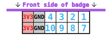
The PMOD connector is wired up to the iCE40 FPGA. Note that while the connector is physically located on the backside of the badge, it has been wired up such that the PMOD’s top side must be pointed in the same direction as the badge’s top.
| PMOD pin | ICE40 pin | Note |
|---|
| 1 | 47 | IOB_2a (paired with PMOD pin 7 IOB_3b_G6) |
| 2 | 48 | IOB_4a (paired with PMOD pin 8 IOB_5b) |
| 3 | 4 | IOB_8a (paired with PMOD pin 9 IOB_9b) |
| 4 | 2 | IOB_6a |
| 7 | 44 | IOB_3b_G6 (paired with PMOD pin 1 IOB_2a) |
| 8 | 45 | IOB_5b (paired with PMOD pin 2 IOB_4a) |
| 9 | 3 | IOB_9b (paired with PMOD pin 3 IOB_8a) |
| 10 | 46 | IOB_0a |
Chips
ESP32
| ESP32 GPIO | Direction | Function | Note |
|---|
| 0 | Both | I2S master clock output / UART download select input | Drives I2S DAC / driven by RP2040 through resistor |
| 1 | Output | UART TX | Connected to RP2040 |
| 2 | Both | SD card data 0 | SD card slot |
| 3 | Input | UART RX | Connected to RP2040 |
| 4 | Output | I2S bit clock | |
| 5 | Output | LED data | Connected to the SK6805 LEDs in the kite |
| 12 | Output | I2S LR channel select | |
| 13 | Output | I2S data | |
| 14 | Output | SD clock | SD card slot |
| 15 | Output | SD command | SD card slot |
| 18 | Output | SPI clock | Connected to LCD and FPGA |
| 19 | Output | SD card and kite LED power control | Set high to enable power to LEDs and SD card |
| 21 | Output | I2C clock | Connected to RP2040, BNO055, BME680, Qwiic connector and SAO addon connector |
| 22 | Both | I2C data | Connected to RP2040, BNO055, BME680, Qwiic connector and SAO addon connector |
| 23 | Output | SPI MOSI | Data from ESP32 to LCD / FPGA |
| 25 | Both | LCD reset | Set to output low to reset LCD, leave floating normally |
| 26 | Output | LCD mode | Low: LCD in SPI mode, high: LCD in parallel mode |
| 27 | Output | SPI chip select for ICE40 | Low: select ICE40, high: deselect ICE40 |
| 32 | Both | SPI chip select for LCD | Low: select LCD, high: deselect LCD. Note: output in LCD SPI mode, input in LCD parallel mode |
| 33 | Both | LCD DC (data or command) selection | Note: output in LCD SPI mode, input in LCD parallel mode |
| 34 | Input | Interrupt from RP2040 | |
| 35 | Input | SPI MISO | Connected to ICE40 |
| 36 (SENSOR_VP) | Input | Interrupt from position sensor (BNO055) | |
| 39 (SENSOR_VN) | Input | Interrupt from ICE40 FPGA | |
RP2040
| RP2040 GPIO | Direction | Pull | Function | Description |
|---|
| 0 | Output | | UART0 TX | ESP32 UART |
| 1 | Input | | UART0 RX | ESP32 UART |
| 2 | Both | | I2C1 SDA | I2C bus data (RP2040 is in slave mode) |
| 3 | Input | | I2C1 SCL | I2C bus clock |
| 4 | Input | Up | GPIO | Button: MENU |
| 5 | Input | Up | GPIO | Button: HOME |
| 6 | Input | Up | GPIO | Button: ACCEPT |
| 7 | Input | Up | GPIO | Button: Joystick A |
| 8 | Input | Up | GPIO | Button: Joystick B |
| 9 | Input | Up | GPIO | Button: Joystick C |
| 10 | Input | Up | GPIO | Button: Joystick D |
| 11 | Input | Up | GPIO | Button: Joystick E |
| 12 | Both | | GPIO | ESP32 bootloader mode¹ |
| 13 | Output | | GPIO | ESP32 enable |
| 14 | Both | | GPIO | ESP32 interrupt¹ |
| 15 | Output | | PWM | LCD backlight brightness |
| 16 | Both | | GPIO | Available next to prototyping area |
| 17 | Both | | GPIO | Available next to prototyping area |
| 18 | Both | | GPIO | SAO GPIO1 |
| 19 | Both | | GPIO | SAO GPIO2 |
| 20 | Input | | GPIO | FPGA done |
| 21 | Output | | GPIO | FPGA reset |
| 22 | Input | Up | GPIO | Button: START |
| 23 | Input | | GPIO | LiPo charger state |
| 24 | Output | | UART1 TX | FPGA UART |
| 25 | Input | | UART1 RX | FPGA UART |
| 26 | Input | Up | GPIO | Button: BACK |
| 27 | Output | | GPIO | Infrared LED |
| 28 | Input | | ADC | Voltage measurement: USB input |
| 29 | Input | | ADC | Voltage measurement: Battery |
¹: Set to input normally and force low to activate
ICE40 FPGA
| ICE40 pin | ICE40 GPIO | Direction | Description | Notes |
|---|
| 2 | IOB_6a | Both | PMOD pin 4 | |
| 3 | IOB_8a | Both | PMOD pin 3 | |
| 4 | IOB_9b | Both | PMOD pin 9 | |
| 6 | IOB_13b | Input | UART RX | |
| 9 | IOB_16a | Output | UART TX | |
| 10 | IOB_18a | Output | Interrupt | Active-low |
| 11 | IOB_20a | Output | LCD register select | |
| 12 | IOB_22b | Both | RAM SPI D2 | |
| 13 | IOB_24a | Both | RAM SPI D1 | |
| 14 | IOB_32a_SPI_SO | Output | SPI MISO | |
| 15 | IOB_34b_SPI_SCK | Input | SPI SCK | |
| 16 | IOB_35b_SPI_SS | Input | SPI SS | |
| 17 | IOB_33b_SPI_SI | Input | SPI MOSI | |
| 18 | IOB_31b | Output | RAM SPI CS | |
| 19 | IOB_29b | Output | RAM SPI SCK | |
| 20 | IOB_25b_G3 | Both | RAM SPI D3 | |
| 21 | IOB_23b | Both | RAM SPI D0 | |
| 23 | IOT_37a | Output | LCD write | |
| 25 | IOT_36b | Input | LCD frame sync | |
| 26 | IOT_39a | Output | LCD data 0 | |
| 27 | IOT_38a | Output | LCD data 1 | |
| 28 | IOT_41a | Output | LCD CS | |
| 31 | IOT_42b | Output | LCD data 2 | |
| 32 | IOT_43a | Output | LCD data 3 | |
| 34 | IOT_44b | Output | LCD data 4 | |
| 35 | IOT_46b_G0 | Input | 12MHz clock | |
| 36 | IOT_48b | Output | LCD reset | Active-low, drive open-drain |
| 37 | IOT_45a_G1 | Output | LCD data 5 | |
| 38 | IOT_50b | Output | LCD data 6 | |
| 39 | RGB0 | Output | LED | |
| 40 | RGB1 | Output | LED | |
| 41 | RGB2 | Output | LED | |
| 42 | IOT_51a | Output | LCD data 7 | |
| 43 | IOT_49a | Input | LCD mode | Should be driven by ESP and monitored by FPGA |
| 44 | IOB_3b_G6 | Both | PMOD pin 7 | |
| 45 | IOB_5b | Both | PMOD pin 8 | |
| 46 | IOB_0a | Both | PMOD pin 10 | |
| 47 | IOB_2a | Both | PMOD pin 1 | |
| 48 | IOB_4a | Both | PMOD pin 2 | |
1.2 - MCH2022 Badge Hardware Hacking
The badge is made for hacking, and the hardware is no exception. There are several intended ways to extend the badge, next to unlimited unintented ones.
If you have access to a 3D printer, an easy and worthwile hardware mod is to
print a knob for the joystick, such as this
one or a case.
Shitty Add-on
The badge has a SAO header,
which can provide power, I2C, and 2 GPIOs to small accessories that can be plugged in.
Qwiic
At the back of the badge there is a Qwiic connector hooked up to the ESP32 that is compatible with a large family of modules from Sparkfun, Adafruit and others.
PMOD
On the side of the badge there is a PMOD connector hooked up to the FPGA that is compatible with a large family of modules from Digilent and others.
May Contain Hardware Area
On the back of the badge there is a prototyping area with a grid of pads, as well as pads the expose I2C, power, and GPIOs.
Across the rest of the PCB are labeled pads that expose things like the LED serial data, audio signal, IR signal, various debug pads, and more.
2 - Getting Help (and helping)
You’re on the main documentation site for The Badge.
We hope that we’ll be able to centralize all documentation efforts here,
but who knows what happens at camps.
We would be very happy to accept pull request (TODO link to how to make a
good PR) if you find the documentation lacking and feel you are able to
make improvements. The documentation project lives in this github
repository
Random Resources for Getting Help
Overview of the main github Repos you can contribute to …
You can find the sources and hardware files for all Badge artefacts
files under the Badge.team organization:
Non-Specific Resources
(TODO)
- ESP32.com
- reddit/r/esp32
- rp2040 (todo)
- micropython
- lattice
- yosys fpga getting started general
2.1 - Troubleshooting & FAQ
This page is intended to collect answers to questions that pop up frequently and
solutions to common problems…
MicroPython crashes every time I connect to it …
Apparently I’m disturbing the Guru’s Meditation
In case you are trying some Python samples and the firmware crashes … like this:
Guru Meditation Error: Core  0 panic'ed (Interrupt wdt timeout on CPU0).

Core  0 register dump:
PC      : 0x40084b56  PS      : 0x00050035  A0      : 0x400d7fde  A1      : 0x3ffbe990
A2      : 0x00040040  A3      : 0x3ffb27e0  A4      : 0xc0000000  A5      : 0x3ffbe970
A6      : 0x3ff40000  A7      : 0x3ffbf074  A8      : 0x800d7fde  A9      : 0x40090908
A10     : 0x00000000  A11     : 0xa6000000  A12     : 0x00000000  A13     : 0x00000473
A14     : 0x3f403a98  A15     : 0xffffffff  SAR     : 0x0000001f  EXCCAUSE: 0x00000005
EXCVADDR: 0x00000000  LBEG    : 0x4000c2e0  LEND    : 0x4000c2f6  LCOUNT  : 0xffffffff
Core  0 was running in ISR context:
EPC1    : 0x400d3f03  EPC2    : 0x400d7fde  EPC3    : 0x00000000  EPC4    : 0x00000000


Backtrace:0x40084b53:0x3ffbe9900x400d7fdb:0x3ffb27e0 0x401d505f:0x3ffb2800
We are working on it:
- make sure you’ve updated your BadgePython to the newest version. Use the
AppUpdate menu item… - try deleting Python from the
Apps menu and reinstalling it from The Hatchery (Hatchery->ESP32->Utilities)
If none of this helps, here’s an easy work around … Connect to the serial console before you start Python. While you’re still in the launcher, connect, you will see some of the logging of the launcher application, when you start Python, you will see the boot messages. If the serial console is already attached when Python starts, it doesn’t crash. WTF!? ¯\_ (ツ)_/¯
I keep getting 419 errors in the Hatchery!
If you can’t log in to the Hatchery (or create an account) or whatever because you are getting 419 Expired errors, you need to either clear all cookies for the Hatchery, use incognito mode to connect or try a different browser. Please also report your experience, inlcuding time of occurance in the issue concerning this behavior to help figure this out.
My SD-Card is not being recognized
Try formatting the card as FAT32. Unfortunately exFAT is currently not supported.
The wifi doesn’t work!
Your battery is probably too close to the ESP32 “tin can”. Try moving it over
:) The black strip on top of the can is the wifi antenna, you need to make sure
that bit is not covered by anything.

The kite in the front is flashing RED!? Am I in danger!?
You’re probably fine. But be sure to drink plenty of water.
But you will need to:
- Download the the RP2040 coprocessor firmware U2F
- Turn the Badge off ( with the switch labeled ON-OFF)
- Hold the
SELECT button while turning the switch back to ON - Make sure a USB cable is connected to your computer
- The Badge will mount as a mass storage device (MSD, a.k.a USB thumbdrive)
- Drag-n-drop (or whatever it is you Linux-from-Scratch folks do …) the U2F firmware onto the drive
This sounds way more complicated than it is, you’ll figure it out. In case you
don’t that means we msessed up something else as well, please bring your Badge
to the Badge tent so we can
have a look to see what went wrong.
The badge doesn’t connect to the computer
If you have followed the instructions concerning udev
rules, you may
have a bad USB cable. Or a charging only cable. Did you make sure to connect
one end of the cable into the computer and the other into The Badge? Try
running lsusb, it should contain an entry like the one below:
$ lsusb
...
Bus 002 Device 025: ID 16d0:0f9a MCS MCH2022 badge
...
If instead, you see a line like this:
Bus 002 Device 027: ID 2e8a:0003 Raspberry Pi RP2 Boot
You may be having some issues with the Bootloader, have a look
here for some hints.
Try running lsusb without a badge and see if you get different messages when
a Badge is connected.
If this is not the case, try out a friend’s cable.
Your badge is probably not broken. Try updating the OS first. Choose “OS
Update” in the main menu.
OMGWTFBBQ “FAIL”!?
In case you see this when first booting your Badge:
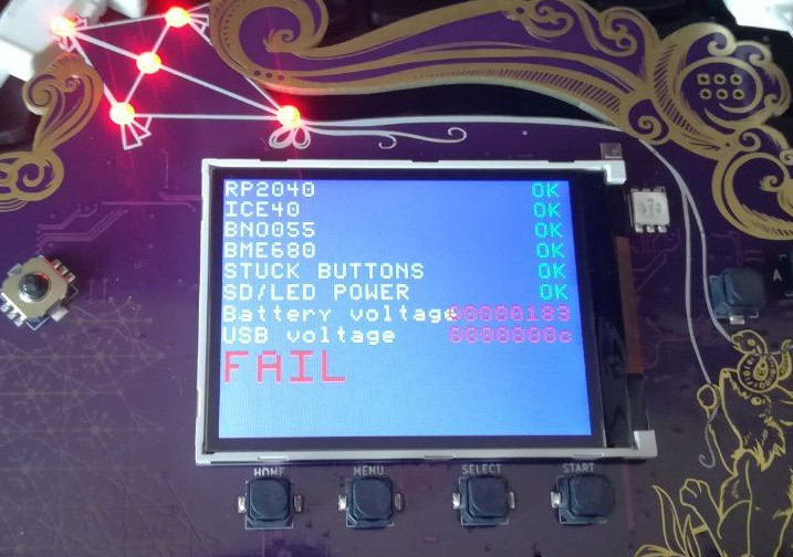
Don’t worry, that just means one of the elves in Santa’s workshop forgot to
confirm that the self-test passed. Plug it into USB, and press A.
3 - Getting started
Congratulations, you’re the proud owner of a shiny new MCH badge! It’s a
fully-functional computer, and while you (can do stuff with it) out of the box,
the real fun starts when you start hacking it. The badge has two processors, an
FPGA and a ton of sensors and toys to play with all in the palm of your hand! And
we’ve done what we could to make using it as friendly and intuitive as
possible. We had a lot of fun making it, and we hope you’ll have a lot of fun
using it.
No fluff! I wanna get started!
Hook up the battery to the badge, the connector only allows it to be connected
the right way around. Set the labeled on/off switch to ON. Things should
quickly start up, display works and it makes a sound.
If this is the case everything works and you’re good to go. Attach the battery
to the badge using the included velcro, slap on the lanyard (and possibly insert an SD-Card) and Start
Hacking!
Don’t forget to update the OS and preinstalled apps. And have a look at some
general tips for Using the Badge.
The rest of this page contains more detailed instructions in case you run into
problems.
In the pack
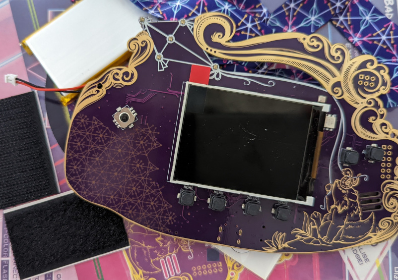
If you are reading this at MCH, you received the unassembled badge in a
bag when you entered the camp. Inside the bag are the following items:
(These will obviously change subject to what is in the pack)
- The badge itself
- A lithium-polymer battery for the badge
- A self-adhesive Velcro patch for attaching the battery
- A printed badge lanyard
- A leaflet containing basic information about the badge
Fitting the battery

The battery is a silver pouch with a short cable terminated in a
trailing socket connector. This mates with a PCB mounted plug which
you’ll find on the component side of the badge. Place your badge screen
side down with the USB-C connector facing towards you, and you’ll find
the on-board battery connector at the bottom right next to a field of gold
squares (the prototyping area -> link to hardware).

The trailing plug on the battery has a small lug on one side that
interfaces with a notch in the on-board socket. With the lug facing
upwards, carefully slot the two connectors together.
Now turn the badge on. The switch is labeled ON OFF and located just
below the battery connector. It will boot up, the display will start
displaying things and the speaker will make some noise.
The battery should now be attached to the badge via the connector. We’ve
provided velcro so you can affix it to the badge more firmly. One side
of the battery tends to buldge, so try out which side lies most snugly
against the badge. Find a good spot on the back of the battery and the
reverse of the badge to attach the velcro.
Inserting an SD-Card
The SD-Card holder is a bit fiddly. We’ve assembled an illustrated
guide to inserting an SD-Card.
Now what?
You should now have a working badge. We strongly suggest that you hook it up to
a live USB power source to fully charge the battery. You’ll need a cable with a
USB-C at the Badge end.
While the battery is charging, it’s time to explore the badge a little.
When you turn it on it will start with a splash screen and details of
all the sponsors who have made the event and the badge possible. You’ll
then see the badge menu screen, so now’s a good time to move along to the
next step in this introduction: using the MCH 2022 badge.
Also, as with all security critical devices, make sure
you update the Badge software and any of the apps you installed. There’s a menu
item for that, which will probably save you a lot of grief from bugs we’ve
already fixed!
3.1 - Inserting an SD Card
I inserted the card correctly, but it doesn’t work.
Format the card as FAT32 not exFAT, please. And if you are using a
humongous 12TB Super SD Card, maybe try a cheap, small one from the grocery
store :)
Oh well, better luck next time! Don’t feel bad, you’re not alone.
You can probably stick it back into the little grey plastic thingie.
Lucky you! You’ve come to the right place.
The trick is to:
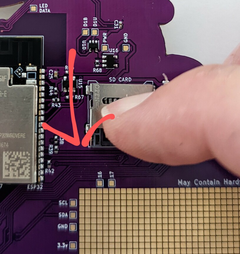
insert a fingernail into the SD-Cardholder manipulation slot and pull DOWN!
(DOWN is in the direction of the arrow in the picture.)
Somehow I never realized the metal thingie actually has “OPEN->” embossed in it
until I uploaded the picture for the documenation. Don’t I feel stupid …
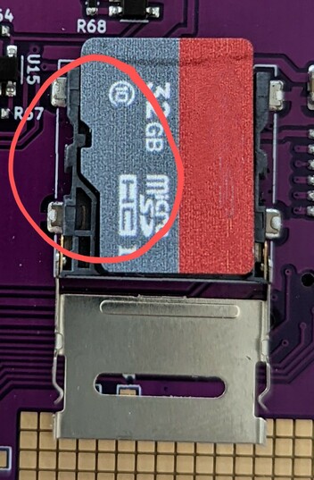
- fiddle around with your SD-Card to somehow get the alignment slot of the grey
plastic thingie to align with the alignment notch in the card.
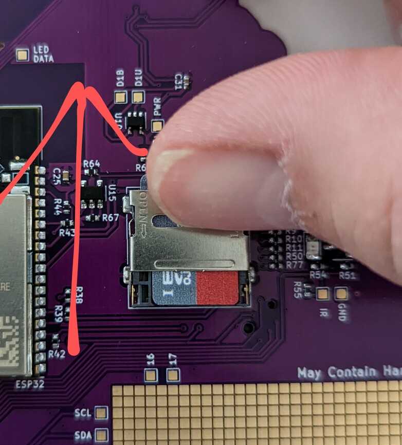
- find a small-fingered nerd to hold the SD-Card in place while you flip the
metal fastener over the card and insert a fingernail into the SD-Cardholder
manipulation slot and push UP! (UP is the direction of the arrow in the
picture)
3.2 - Installing Apps from "The Hatchery"
WTF is a Hatchery!?
The Hatchery is an app store for The Badge!
You can also sort through the apps other people have published there. If you
do so, please be aware that we don’t check for malware and will NEVER ask for
your credit card number or home banking password (just kidding, off course we
will.)
BTW, it’s called Hatchery because it (used to) contain “eggs” because
previously the Hatchery was limited to Micropython apps and those are called
eggs. And eggs hatch if you don’t eat them. Nowadays the Hatchery also supports
native ESP Apps and FPGA bitstreams.
You can also use the Hatchery to publish your own
apps and share them with friends. And
unlike other App Stores, you don’t need a Dunn & Bradstreet Number, $1000 and
don’t have to worry about your app being rejected because it contains malware.
A Word of Warning
Our crack team of Useability Experts are working around the clock to make the
Hatchery even more intuitive and easy! So some of the information here,
especially the screenshots may be out of date by the time you read this. Also,
the documentation team is exceptionally lazy. Did we mention you can help
update the documentation!? Go to the website
project to create a Pull Request!
Better yet, check out the repo for The
Hatchery itself and make improvements.
In case you are experiencing issues receiving 419 errors, clear
cookies
and try again.
Find an App
This will probably be the challenging part. We recommend you do this on a big computer, like a laptop. Something with a keyboard.
Go to mch20222.badge.team and sift through our
fine offering of Hello World apps and super slow bitcoin miner malware.
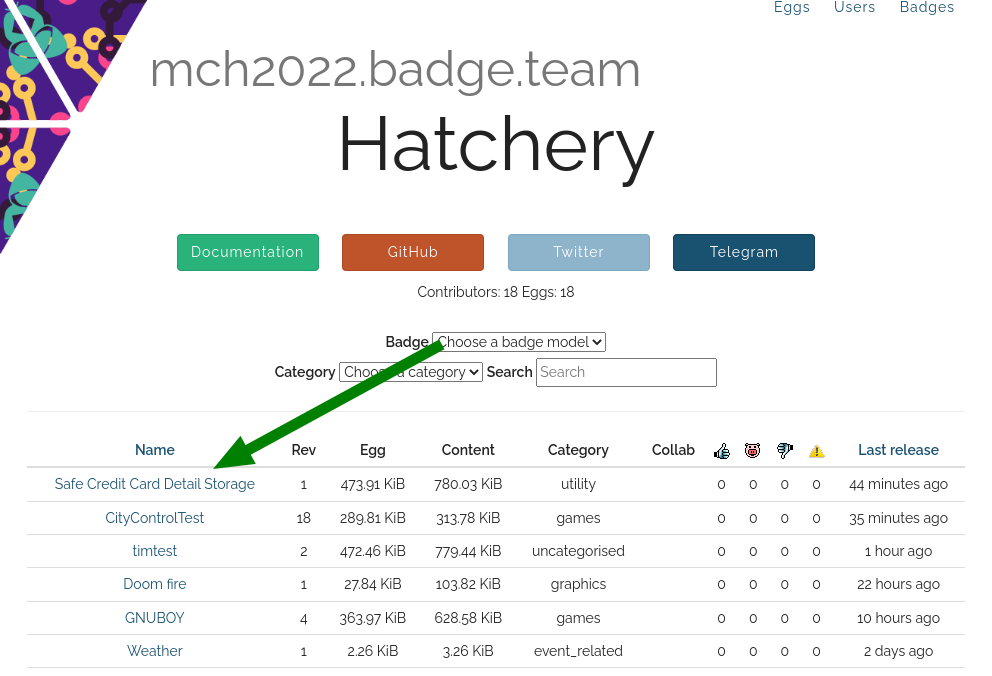
If you go to the apps details page, you can download the app.
But you don’t need to. Just remember the Category.
Now, go to the Hatchery app on the Badge.
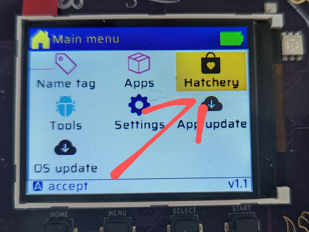
Next you’ll be asked whether you want to install an ESP32 app, a Python egg or
and FPGA bitstream. At the moment you kindof need to guess, here’s a heuristic:
If the details page contains:
- a file named
main.bin it’s ESP32 - a bunch of Python files, it may be Python
- a file named
bitstream.bin it’s an FPGA bitstream
In the next step, go to the Category remembered. Let’s pick “Safe Credit Card
Detail Storage” (ESP->Utility). That sounds totally legit! Select it with the
A button and you will see app details. As you can see, the app is, in fact,
totally legit.
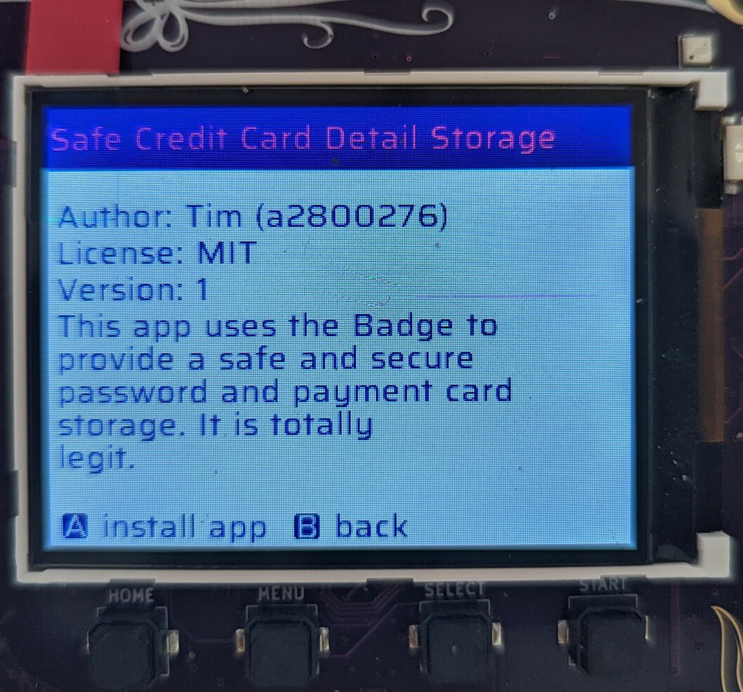
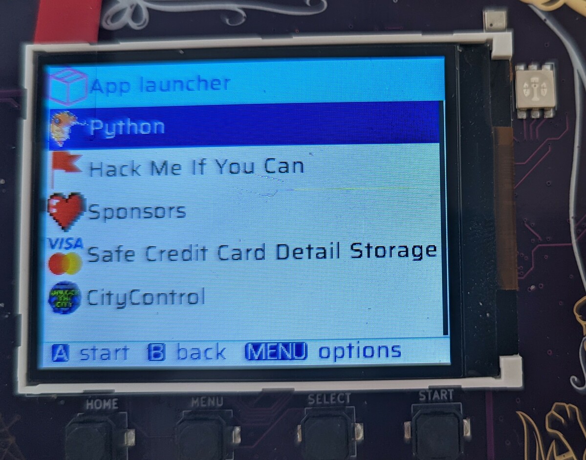
Now just press A to install. It will download for a while.
Once it’s done, go to the “Apps” menu and your brand new app should be
available to launch! Or … uninstall.
3.3 - Using Your Badge
Your MCH badge comes with installed software which allows you to select and run
applications, install new applications from the online Hatchery, and configure
Badge functions such as the Wi-Fi SSID and password (don’t worry, it can
connect to camp Wifi out of the box).
This page is a high-level introduction to the installed software. If you came
here looking for details on how to write software for the badge, then take a
look at our software development guide.
When you first turn on your badge, you’ll see a series of logos of the MCH2022
sponsors (Thanks again!) before finally a chime plays on the speaker and you
find yourself at the main menu screen. It’s a graphical launcher with a series
of icons for the different Badge functions. You can select a function with the
joystick before launching it with the A button or by clicking the joystick.
When you are in an app the convention is that the A button is usually an
action, the B button should take you one step back, and the Home button at the
bottom left of the screen should take you out of the app and back to the menu.
As shipped, the badge has seven options on the main menu:
- Name Tag. This is the usual name tag app for an event Badge.
- Apps. This takes you to the user-installed apps on The Badge, including a
Python launcher for backwards compatibility with previous Badge.team badges
going back to the SHA 2017 badge.
- Hatchery. This is the app store for The Badge. Explore it to find new apps
written by other MCH attendees.
- Tools. Here you can find a file browser, as well as infra-red remote control
apps for some of the camp lighting.
- Settings. This takes you to a selection of badge configuration options. The
badge ships pre-configured for the MCH2022 network, however it’s on this menu
that you can find the tool to reconfigure it for your home network.
- App update. This option updates the apps on your badge to their latest
versions from the hatchery.
- OS update. Here you can update the badge firmware.
4 - Software Development
Introduction …
This is a shameless placeholder for the software development section.
There are roughly 3 to 5 ways to develop for the Badge (depending on how
you count:)
- Micropython : write apps in Python! This is the easiest way to
get started, with the additional benefit that you probably don’t need to
install anything (or much). Actually this should be the easiest way, but
unfortunately has the fewest docs. Have a look
here
for documentation of the Python modules on the Badge.
- ESP-IDF : native EPS apps using the IDF (IoT Development
Framework)
- FPGA : this is the special feature … not happy with the Tensilica
CPU on the ESP? Just implement your own RISC-V core (or, to get started,
connect all the buttons together with an AND gate…)
The other two plus (depending on how well you can count) :
- RP2040: aka Raspberry Pico. This is an onboard conprocessor that we
are using as our USB Lifeline to the outside world. As such, if you break
stuff here, you can easily brick your badge. Feel free to play around with
it, but be aware: THIS VOIDS YOUR WARRANTY … and not in a fun way. It’s
very unlikely we’ll have the resource to help you fix the badge during the
camp.
- RISC-V and
Forth:
Because the badge contains an FPGA, you can turn it into anything you want.
Technically the RISC-V and Forth projects are just FPGA projects, but the
RISC-V CPU is powerful enough to run a Mandelbrot and Tricorn fractal explorer.
A different RISC-V processor implementation with a focus on performance instead of readability can even run Doom!
The Forth includes a custom stack processor and besides being useful for
interactice experiments with freshly soldered additions on the PMOD connector, it can run a game of
Snake.
- Rust: just a hint or two to get you started. Ask around the Telegram channel if you need support.
- TinyGo: Some hints on getting started with TinyGo on the Badge and some samples …
- Arduino: this was intended to be done and beautifully polished …
but then we all got COVID and couldn’t finish. You can try to develop apps
with Arduino if you think it will be easier, but it will probably cause some
pain. Of course, we would be ecstatic if you help getting it work smoothly.
Linux permissions
Regardless of the way you’re going to program the badge, to connect to the badge over USB from Linux, do the following.
Create /etc/udev/rules.d/99-mch2022.rules with the following contents:
SUBSYSTEM=="usb", ATTR{idVendor}=="16d0", ATTR{idProduct}=="0f9a", MODE="0666"
Then run the following commands to apply the new rule:
sudo udevadm control --reload-rules
sudo udevadm trigger
Windows installation
To upload programs to the badge with the provided tools, python and pyusb are needed. The easiest way to install these on windows is by installing miniconda
After installation, open “Anaconda prompt” from the start menu. Then do the following
conda create -n badge -c conda-forge python pyusb
conda activate badge
Now you should be able to run commands like:
python ".\Desktop\mch2022-tools-master\webusb_fat_push.py" .\Desktop\my_test.py /flash/apps/python/button_tester/__init__.py
Micropython
The Badge comes with a preinstalled Micropython interpreter. Python
should be the easiest way to control the device and the easiest mode to
write apps for The Badge, especially if you are a beginner or don’t want
to spend a lot of time downloading toolchains and debugging drivers.
Before the Camp and if you are afraid to break things…
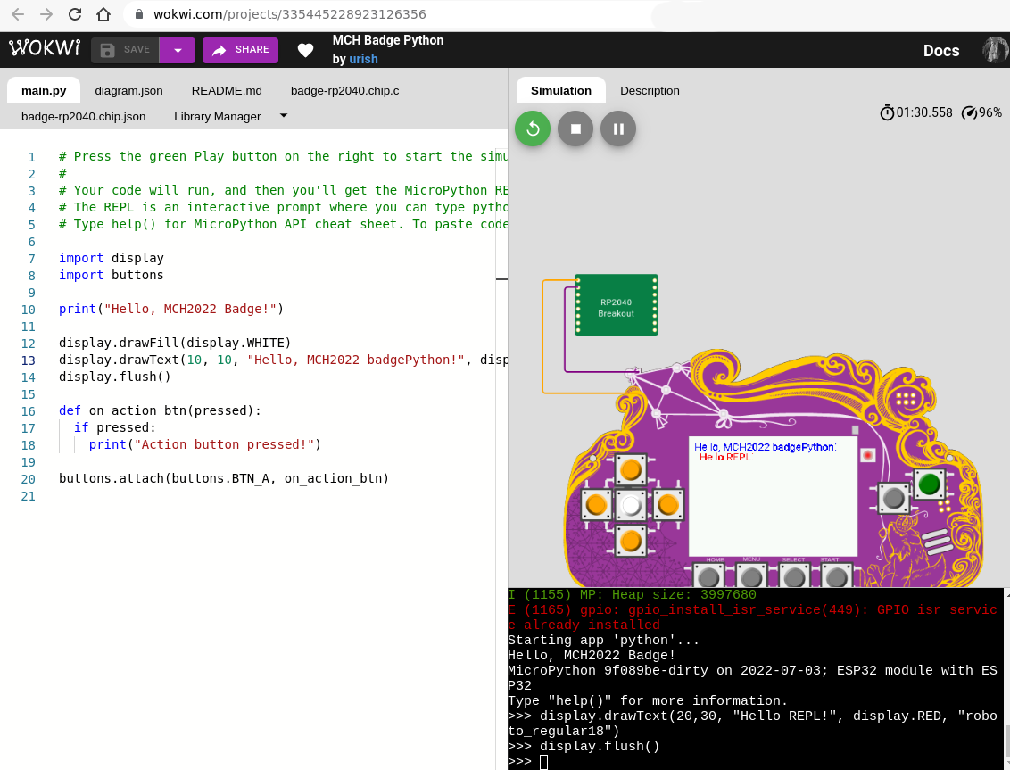
Uri Shaked a.k.a Wokwi built
an awesome emulation of the badge that runs in your browser. You can use it to
test stuff out if you don’t yet have a Badge or your Badge is being used for
something else. Or if you just feel more comfortable with a Badge that can’t
catch on fire. It fantastic, you can click the buttons and everything! Try it.
On the device!
First, make sure Python is installed and that you didn’t accidentally
delete it. Check in the apps menu. If it’s not there: install the
Python app from the Hatchery by going to Hatchery -> ESP32 native binaries -> Utility -> Python and install it either onto the flash or
onto an SD card.
This badge contains a common ESP32 firmware platform shared with other
badges, so to learn more about the general platform and its components,
start
here.
In addition there is also a mch22 module that offers a few
badge-specific APIs.
While the above allows you to access the Python shell and install Python
apps from the hatchery, here is how you upload custom apps to the badge
over USB:
- Download mch2022-tools
- Write you Python code using the platform modules documented above
- Use
python3 webusb_fat_push.py __init__.py /sdcard/apps/python/myapp/__init__.py - Start your app in the Apps menu.
There’s a more detailled description on Micropython development here.
4.1 - Developing native Badge apps with the ESP-IDF
Introduction
Even though MicroPython is a quick and easy way to write apps for the Badge,
you are limited both in terms of performance and functionality. If you need or
want to write native applications, you have found the right place. This section
describes how to develop Badge apps using the ESP-IDF, the development
toolchain for native ESP32 apps.
Should I write a native app?
TLDR: OF COURSE YOU SHOULD! It’s fun! Hey, this Badge is for an event
called “May Contain Hackers”, it was made for hacking in every possible way!
Native apps are amazing. The beautiful sponsors
slideshow that you
saw when you first booted your Badge was a native app. The BadgePython
interpreter that runs all the
BadgePython Eggs is a native app. Native apps are not launched within the Badge
firmware - they are directly mapped to memory and then the Badge is rebooted.
In other words: No walls, no fences around you. Ideally suited for writing
Badge malware! Your code runs directly on the metal. This makes native apps the
perfect option if you need full power and/or full access to all the MCU’s
peripherals, not just the ones with a Python wrapper.
However, this comes at a (small) price: As native apps need to be directly
accessible to the ESP32, their binaries reside in a special partition in the
module’s internal Flash memory (if you’re interested in the magic behind it,
have a look at the AppFS
component). Because they
are standalone firmwares, they tend to be larger than simple MicroPython apps.
As a consequence, there is a limit to how many native apps can be installed on
a Badge (five-to-ten-ish, depending on code size). If you run out of memory,
you will have to uninstall others.
Getting Started
If you want to dive right in, here’s a short example walktrough to quickly get
started writing a native ESP-IDF app.
Template App
The template app is a public template repository to use as a basis for your own
app. It contains an application skeleton, an appropriate version of the ESP IDF
and components for common Badge peripherals. You can find the template app on
github. All examples here
use this template. Basically: Clone, build, install, publish, fun.
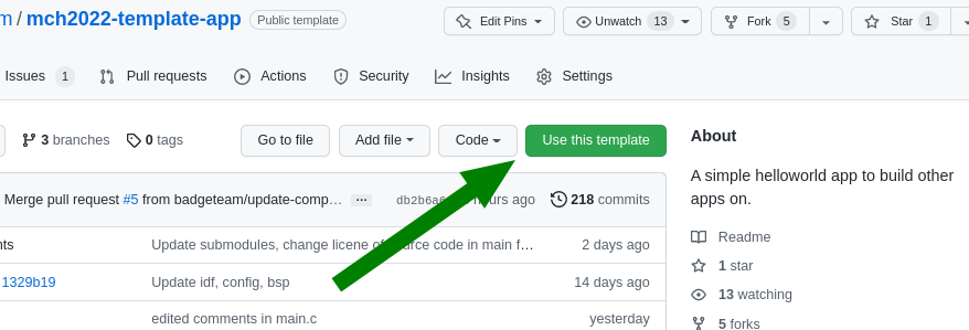
Incidentally, the template app has a button you can use to create a clone for
your github user.
A More Advanced Example
Once you are familiar with the template and getting started example, it’s time
to move a step further. The ESP-IDF has tons of features to offer. Here’s
a more advanced app which turns your badge into
a (crappy) bluetooth speaker.
4.1.1 - ESP-IDF getting started
Programming native applications on the Badge requires an ESP
IDF to
be installed. IDF stands for “IoT Development Framework” and is Expressif’s
SDK which provides:
- convenient access to hardware functionality
- implementation of protocols such as TLS, HTTP and MQTT which are
commonly used in IoT projects
- common utilities such as logging, error handling and JSON parsing
- infrastructure code for building, flashing and debugging.
The IDF will be installed automatically (via git submodules and make commands which we
will point out) but it does require some dependencies to be installed.
Installing Prerequisites
How to install these prerequisites is described on the IDF documenttion page for:
The instructions will (mainly) install git, cmake and python. Remember you DO
NOT have to install the IDF!
In order to sideload the apps you develop, you will be using our webusb
tools. These tools will get
automatically installed, but require pyusb to be installed. This can be
installed with pip install pyusb or apt install python3-usb
Download & build the “template app”
We created a basic Hello World template
app that’s intended to be
used as a basis for native badge apps you build. To allow you to get started quickly, the
template app downloads the IDF in the required version, as well as some badge
specific components you will.
To clone the template app, open a shell:
$ git clone https://github.com/badgeteam/mch2022-template-app my_fancy_app_name
$ cd my_fancy_app_name
The
Makefile
in the template app contains a number of targets for your convenience:
prepare : Download all the ESP32 dependencies needed to build, you only need to run this once!build : compile the codeinstall : install the app you just compiled (NOTE: if you have previously
used the IDF to build ESP32 code, this is different from regular flashing! see below)monitor : connect to the ESP32 console and look at your log files.
$ make prepare # this downloads all the dependecies and may take a couple of minutes

$ make build   # this compile your app
$ make install # this installs the successfully compiled app to a connected badge.

# you really only need '$make install' because it depends on `install`.
It will take a couple of minutes to download all the components. Once completed, a simple app
showing “Hello, World!” will run on your badge.
Difference to “normal” IDF
If you have previously used the IDF, you may have noticed that we don’t use idf.py flash to
install the app on the Badge. (And if you haven’t, you can safely skip this section. :)
The idf.py flash command assumes that the binary to flash is the main
application for the device. This is not the case for the Badge, though. The
main application is the
launcher app, i.e. the
app with the menu that starts by default. The make install target of the
Makefile copies our newly created app into the
appfs
instead of overwrting the launch. Once copied to the appfs, the launcher can
find it and the app should appear in the apps menu.
Obviously you can use idf.py flash but you’ll delete the launcher
app and would need to reinstall it later.
Customizing the template app
Finally! Now that we have all the bureaucracy taken care of, we’ll start off by
modifying the message printed to the screen. Have a look at this
line
of main.c, you can see the text shown on screen:
//...
        // This text is shown on screen.
        char             *text = "Hello, World!";
//...
This part is responsible for drawing the text to the screen.
Go ahead and try to edit the text, here shown as “Fancy App!”:

The buttons on the Badge are not directly connected to the ESP32, instead they
are read by the rp2040 coprocessor via I2C. Have a look in the
esp32-component-mch2022-rp2040
component in case you are interested in the details.
The button handler starting on this
line
of main.c currently causes the app to exit and return to the launcher
whenever the HOME button is pressed.:
        //...
        // Await any button press and do another cycle.
        // Structure used to receive data.
        rp2040_input_message_t message;
        // Await forever (because of portMAX_DELAY), a button press.
        xQueueReceive(buttonQueue, &message, portMAX_DELAY);

        // Is the home button currently pressed?
        if (message.input == RP2040_INPUT_BUTTON_HOME && message.state) {
            // If home is pressed, exit to launcher.
            exit_to_launcher();
        }
        // Is the home button currently pressed?
        if (message.input == RP2040_INPUT_BUTTON_HOME && message.state) {
            // If home is pressed, exit to launcher.
            exit_to_launcher();
        }
        //...
Let’s change this behaviour so the screen is briefly pink after pressing the A button.
Graphics for the badge are handled by a library called Pax, if you want to dig deeper
have a look at the docs here
Pax uses the same RGB (well, ARGB, to be precise) hex triplets as HTML.
0xeb34cf is beautiful MCH pink.
//...
        // Button handling.
        if (message.input == RP2040_INPUT_BUTTON_ACCEPT && message.state) {
                // Make a pink background.
                pax_background(&buf, 0xeb34cf);
                // Update the screen.
                disp_flush();
                // Wait for half a second.
                vTaskDelay(pdMS_TO_TICKS(500));
                // After this, it loops again with a new random background color.
        } else if (message.input == RP2040_INPUT_BUTTON_HOME && message.state) {
            // If home is pressed, exit to launcher.
            exit_to_launcher();
        }
//...

Using WiFi
The template app you’ve been playing with has a simple WiFi connection
API.
First, empty the while loop so it looks like this:
//...
    while (1) {
        // Await any button press and do another cycle.
        // Structure used to receive data.
        rp2040_input_message_t message;
        // Await forever (because of portMAX_DELAY), a button press.
        xQueueReceive(buttonQueue, &message, portMAX_DELAY);

        // Is the home button currently pressed?
        if (message.input == RP2040_INPUT_BUTTON_HOME && message.state) {
            // If home is pressed, exit to launcher.
            exit_to_launcher();
        }
    }
//...
Instead of writing “Hello World” to the screen, we will modify the code to
change the background color to indicate our Wifi connection status. Call
wifi_connect_to_stored() to connect to WiFi and set the background color
depending on whether the function returned successfully.
//...
    // Init (but not connect to) WiFi.
    wifi_init();
    // Now, connect to WiFi using the stored settings.
    bool success = wifi_connect_to_stored();
    if (success) {
        // Green color if connected successfully.
        pax_background(&buf, 0xff00ff00);
    } else {
        // Red color if not connected.
        pax_background(&buf, 0xffff0000);
    }
    disp_flush();
//...


What you want to do with WiFi varies a lot, so we can’t explain that here. But
if you have other libraries that need WiFi (for example an MQTT client), you
start them after this code.
Sharing is caring!
Now you’re ready to publish your app in the Hatchery. Follow these instructions to publish your app.
For further information:
4.1.2 - A More Advanced Example
If you have reached this page, you have probably already had a look at the
template app and played
through the getting started tutorial. If not, it
might be a good idea to do it now - there’s a lot of information on getting the
prerequisites installed.
You will need a computer with libusb, pyusb, git, cmake, make, python3, a
terminal, a web browser and a text editor. This should be easily doable on
Linux machines and Macs - if you’re on Windows, it’s probably easiest to work
in a Linux wrapper but YMMV. Additionally, a github account is helpful but not
strictly needed. Check here for details.
This journey assumes that you have some basic familiarity with shell, C and git
(or a search engine of your choice). This is not a line-by-line tutorial, it
just gives you the rough outline of writing an app and discusses some
approaches and techniques along the way. If you want to cheat and download the
finished project, go here
Starting
Start by cloning the template
app - go there, click on
“Use this template” and follow the instructions to make your own copy (or you
can clone the repo and add a new remote manually). git clone the repo,
cd to it and run make prepare. This should set up the ESP-IDF and
all badge-specific components.
What should we do?
If you’re not sure what you want to hack, the ESP-IDF examples are an
amazing starting point. They are already on your machine: ls esp-idf/examples.
Hours of happy browsing. Besides covering many features of the ESP32, they are
exceptionally well written and documented (usually).
We’ll use one of these app to build our app - something that can’t be done in
the BadgePython world: Let’s turn the Badge into a bluetooth Boom Box. Speaker
sound quality will most likely be worse than any smartphone on this planet,
but with the headphone output, this thing might even be usable for something.
There’s a working example at
esp-idf/examples/bluetooth/bluedroid/classic_bt/a2dp_sink.
The code example already shows how to hook the audio stream to an I2S
(Inter-IC
Sound)
DAC. And conveniently, the Badge’s audio outputs are connected to an I2S DAC!
Almost like we’re done already before we even started.
Shameless Copying
To get started, copy the following files from the IDF project’s main directory:
bt_app_av.h, bt_app_av.c, bt_app_core.h, bt_app_core.c into your own
main folder (they are Public Domain, after all!). And while you’re at it,
copy most of the contents of the main.c file over to the end of your main.c
file and the includes to the top.
Actually Hacking Some Code …
Start by integrating the bluetooth initialization routine into your app. Rename
the bluetooth example’s app_main to bt_init and call it within our
app_mainfunction in place of the call to wifi_init ( we won’t be
using WIFI in this example). bt_init must be declarated above app_main
code. Either move the whole function up, or add a declaration.
Unfortunately, both app_main and bt_init call nvs_flash_init.
And nvs_flash_init may only be called once. Get rid of the second
call.
The example projects defines a number of constants using menuconfig. These
are defined in
Kconfig.projbuild,
but we don’t need them. For example, this mechanism in the original IDF example
allows you to redefine the I2S pins to use, but these are hardwired on the
Badge, so configuring them adds unnecessary complexity. grep through main.c
looking for CONFIG_EXAMPLE and replace them:
CONFIG_EXAMPLE_A2DP_SINK_OUTPUT_INTERNAL_DAC : should be false, this option would route the audio to the ESP’s internal DAC, but the Badge has a dedicated audio DAC chipCONFIG_EXAMPLE_I2S_BCK_PINCONFIG_EXAMPLE_I2S_LRCK_PINCONFIG_EXAMPLE_I2S_DATA_PIN
We need to find the new values for the I2S pins
CONFIG_EXAMPLE_I2S_BCK_PIN, CONFIG_EXAMPLE_I2S_LRCK_PIN and
CONFIG_EXAMPLE_I2S_DATA_PIN in i2s_pin_config_t. Obviously, you can
find the pins in the hardware
schematics,
but there’s an easier way: Have a look at
components/mch2022-bsp/include/mch2022_badge.h.
The Badge’s board support package has defines for all pins. (Note: At time of
writing, this header had LRCLK and BCLK swapped, but hopefully this will be
sorted out soon).
The components directory is generally a good place to look if you’re
looking for Badge drivers. All items in this folder are independent components.
You can imagine them as libraries. They are automatically added to the project
by the ESP-IDF build system.
I2S has some sloppy signal naming rules, which may be confusing. LR is LRCLK (a
word clock), CLK is BCK (a bit clock) and DATA is DATA. In addition, our DAC
wants a MCLK (usually faster than the bit clock), so we add an entry:
.mck_io_num = GPIO_I2S_MCLK. In the end, it should look something like
this:
    i2s_pin_config_t pin_config = {
      .mck_io_num = GPIO_I2S_MCLK,
      .bck_io_num = 4, // should be GPIO_I2S_CLK
      .ws_io_num = 12, // should be GPIO_I2S_LR
      .data_out_num = GPIO_I2S_DATA,
      .data_in_num = -1 // not used
    };
    i2s_set_pin(0, &pin_config);
While you’re at it, you can tweak the I2S parameters to our needs (located directly
above the pin_config code). I2S has half a dozen different dialects and
each I2C peripheral speaks a different one. Getting the parameters right is not
hard but tedious, requiring comparison of
datasheets. Additionally, because
the I2S peripheral will stream audio data via DMA, we can adjust buffer
sizes. Here’s some settings that seem to work well:
    i2s_config_t i2s_config = {
      .mode = I2S_MODE_MASTER | I2S_MODE_TX, // TX only
      .sample_rate = 44100,
      .bits_per_sample = I2S_BITS_PER_SAMPLE_16BIT,
      .channel_format = I2S_CHANNEL_FMT_RIGHT_LEFT, // stereo
      .communication_format = I2S_COMM_FORMAT_STAND_I2S,
      .dma_buf_count = 6,
      .dma_buf_len = 128,
      .intr_alloc_flags = 0, // default interrupt priority
      .bits_per_chan = I2S_BITS_PER_SAMPLE_16BIT,
      .tx_desc_auto_clear = true // auto clear tx descriptor on underflow
    };
    i2s_driver_install(0, &i2s_config, 0, NULL);
Almost Ready to Try
We’re close to getting something working. Just four things before we try our first build:
- Change our app name: The projects Makefile contains an
install target.
It’s purpose is to push the project’s binary to the Badge during development.
The name in quotes is the name shown on the Badge’s app chooser. Change it
something unique. - Change the Speaker’s name: There’s a
#define that we copied over from
the bluetooth example: LOCAL_DEVICE_NAME. This is the name broadcast
via bluetooth. Change it to something unique. idf.py menuconfig: menuconfig allows you to enable and configure the
components in your project. First, enable bluetooth. Start the tool with
make menuconfig, go to Component config > Bluetooth and enable it.
Go to Bluedroid Options and enable Classic Bluetooth and
A2DP(Advanced Audio Distribution Profile = what bluetooth speakers do).
Later on, menuconfig is a good place to disable unneeded software
components. For now, we don’t care.- Add files to compile: Remember that we added additional ‘*.c’ files,
bt_app_av.c and bt_app_core.c? The project’s build process works
roughly as follows: make build triggers idf.py build which in
turn uses cmake. For now you don’t need to understand this in
detail,you just have to tell the build system about the new files. We need to
edit main/CMakeLists.txt. When you’re done, the SRCS section
should look something like this:
    SRCS
        "main.c"
        "bt_app_core.c"
        "bt_app_av.c"
Now it’s time to make. Type make prepare, this downloads all the
prerequisite tools and code. This process might take a while. It will fell like
an eternity. Meanwhile, whistle the Jeopary theme song. Drink some water. Wash
your hands. Give a polite, honest compliment to a stranger.
The make process should have finished by now. Now type make build. If this
fails, you probably didn’t follow the steps properly (most likely the
compliment part). No worries, subsequent builds will be faster.
Now, run make install. If there’s an error concerning missing USB, repeat the
libusb and pyusb install steps. If you get a
UnicodeEncodeError in printProgressBar, you’re using a Mac and you
can solve this problem by editing tools/webusb.py: Replace the fill
character with another character, e.g. *. Or fix it and create your first PR
to the tools repo!
If everything went as expected, you should see a WebUSB screen on the Badge and
a progress bar in the terminal. Once upload and verification completes, the
Badge should reboot and show the “Hello world” screen of the template app.
… Boring!
Take your phone or other bluetooth device, scan for new devices. Select
BadgeBoomBox or whatever you chose for your speaker’s name and pair them.
Make sure the speaker switch on your Badge is turned on. Play some music. Hear
it? That amazing sound of no bass? Unbelievable.
Understand What’s Going On
Good work! Let’s take a short break and look at what the app is doing (hey,
we didn’t write much of it yet). ESP-IDF has a logging
facility
that is used in the example code (look for ESP_LOGI, ESP_LOGE,
ESP_LOGD etc.). We can monitor the logs with make monitor (if it
does not work, you might want to set the PORT environment variable to the ESP’s
/dev/tty* ). If you succeed, you will see bluetooth connection and
disconnection events and all sorts of interesting things happening. For
example:
There are “volume change simulation” events. Too bad we didn’t look into the
example before - the example code simulates volume controls and a user
randomly turning the volume up and down to showcase the AVRC (Audio/Video
Remote Control) features. This has to go. But just the “random volume change”
part - we may want to hook the volume control to our
buttons. The simulation is executed in a separate task, look for
s_vcs_task_hdl in bt_app_av.c and surgically remove it from the
source code along with volume_change_simulation.
If you connected specific devices, e.g. an Android phone, you might be
surprised to see that the phone will not only send connect/disconnect and
play/pause events, but sometimes also track titles as well as album and
artist names. Wouldn’t it be great to see this on the screen?
AVRC is not consistently used by all devices. Some features are used, some not.
Anyway, let’s have some fun with it.
Another nice thing to have would be a dB-Meter. Our next task is to sift through
the code to see where the audio stream passes by to analyze it.
Side note: Tasks, Events, FreeRTOS messaging and our threading approach
ESP-IDF makes heavy use of FreeRTOS. Two essential building blocks of FreeRTOS
are Tasks and Queues. Tasks can be seen as threads: Independent,
preemptively scheduled sequences of operation. Each application has a main
thread (the one that executes app_main), a timer thread and possibly other
threads (e.g. for bluetooth, Networking and other things). Queues are often
used to pass events and other information from one task to another. They are
basically thread-safe FIFO buffers. One task (or an interrupt) posts elements
into the queue and another task can wait for elements to arrive in that queue.
The template app already uses one queue: The RP2040 firmware will post
button presses into this queue. The application’s main loop waits for button press
events to arrive and reacts to it by setting a new random color and redrawing
the screen.
The bluetooth stack uses its own tasks. Our task, the main task, controls the
screen and user interaction (and it’s a good idea to restrict this to a single
task). So if we want to receive bluetooth information in the main task, it’s a
good idea to use a queue. bluetooth event -> queue -> main task
reacts.
But our main task is already blocked waiting for the button press queue! How
can we receive our Bluethooth events? Could we use the button queue for our
bluetooth events? Yes you could! But it’s not polite to push things into
other’s queues without prior consent. So we don’t.
There’s another option: Queue sets are used to combine queues and
(other things) and wait on several events simultaneously.
So we’ll create a new audioQueue to send us messages whenever there’s
a relevant bluetooth and/or audio event. We also use this queue to send
audio level updates regularly.
Queue entries can have data attached to them. This is often a struct with an
event type and additional data, typically implemented as a union so that
different events can have different data associated with them. It’s good
practice to keep these entries short because queues will have to allocate
several instances prior to usage (Real Time OSes prefer allocating a fixed
amount of memory at start instead of dynamically allocating memory during
runtime).
To keep the queued data short, we will not include the full audio stack state
in the queue entries. Instead we’ll generate an event to notify that the state changed, but
not what actually changed. For this, we use another mechanism to get data
safely from one task to another: Semaphores used as mutexes / locks. The
bluetooth stack will collect its own state in a struct. The main task can
request a copy of that state struct. All accesses to members of that struct
will be embedded in a lock, making sure that only one task has access to this
struct at any instance in time.
Queues are good for pushing information from one task to another, mutexes are
good for pulling. Admittedly, we could have used just queues in this case, but
this example is supposed to be at least slightly educational…
In addition to the “something changed in the bluetooth audio state” event, we
will have a dB-Meter-update event that should be sent in roughly 20-50Hz
intervals so that we can have a smooth noise meter animation.
Who should manage the queue? The queue could be located either in the
bt_app_*** part or in our main.c. Both are good options. We will
add them to main.c, reasoning that the bt_app_*** is a generic service
and should not make any assumptions about hosting application. As a
consequence, the bt_app_*** part will just issue callbacks whenever
something interesting happens. The code we’ll write in main.c takes care
of queueing these events.
We will leave the well-paved path of documenting every changed part in the code
here. The remaining document will show some examples. As said, the full code is
in the repository.
After some light reading, you’ll quickly get a better overview over the
bluetooth app: naming suggest that bt_app_core.c seems to do the actual
streaming while bt_app_av.c handles metadata and remote control. So the
audio data is more likely to be found in bt_app_core.c. And metadata is
most likely found in bt_app_av.c.
We need to decide: What data is useful for us? What could
we want to display?
- Connection state: Whether we’re disconnected, connected, connecting or
disconnecting
- Audio playback state: Whether we’re playing, stopped or suspended (which is,
in effect, also stopped somehow)
- The current volume: A value between 0..127
- Our current sample rate (no idea if someone is interested but anyway, let’s
collect it)
- Current title, artist and album (if available)
So a simple struct to hold that state should look something like this:
/** the full exposed audio state in a struct */
#define AUDIOSTATE_STRLEN 100
typedef struct BTAudioState_ {
  esp_a2d_connection_state_t connectionState;  // 0=disconnected, 1=connecting, 2=connected, 3=disconnecting
  esp_a2d_audio_state_t playState;  //0=suspended, 1=stopped, 2=playing
  uint8_t volume; //0..127
  int sampleRate;
  char title[AUDIOSTATE_STRLEN];
  char artist[AUDIOSTATE_STRLEN];
  char album[AUDIOSTATE_STRLEN];
} BTAudioState;
So what do we do now? Look into the logs (remember make monitor) for the data
we’re interested in. Find the code that generated the log messsage. Insert
code to update our state. Be sure to lock each access to the struct. After a
change, push an entry to the event queue. It’s a good idea to clear the state
when we get disconnected.
For example, we insert four lines to handle ESP_A2D_AUDIO_STATE_EVT,
an event sent whenever the actual stream is started, stopped or suspended:
    case ESP_A2D_AUDIO_STATE_EVT: {
        a2d = (esp_a2d_cb_param_t *)(p_param);
        ESP_LOGI(BT_AV_TAG, "A2DP audio state: %s", s_a2d_audio_state_str[a2d->audio_stat.state]);
        s_audio_state = a2d->audio_stat.state;
        if (ESP_A2D_AUDIO_STATE_STARTED == a2d->audio_stat.state) {
            s_pkt_cnt = 0;
        }
        lockAudioState();
        audioState.playState = a2d->audio_stat.state;
        unlockAudioState();
        notifyAudioStateChange();
        break;
    }
There are other parts where the state is updated, but they all follow the same
principle, so it would be boring to list them all here. Try yourself! Or have a
look at the repo. lockAudioState()acquires the lock,
unlockAudioState() releases it and notifyAudioStateChang() pushes
an event to our queue.
Tapping the audio stream
bt_app_core.c has two tasks: The bt_app_task that responds to
bluetooth stuff and the bt_i2s_task that seems to stream the audio data
to the I2S peripheral. Bingo! That’s ideal!
Have a look at bt_i2s_task_handler: This function mainly consists of an
endless loop waiting on a ring buffer to deliver sample data and pushes
that data into the i2s peripheral. We can hack that! First, we want to
implement volume control by scaling each sample. Second, we want to calculate
the audio volume. Have a look:
static void bt_i2s_task_handler(void *arg) {
    uint8_t *data = NULL;
    size_t item_size = 0;
    size_t bytes_written = 0;
    static float leftSquares = 0;
    static float rightSquares = 0;
    static int sampleCount = 0;

    for (;;) {
        /* receive data from ringbuffer and write it to I2S DMA transmit buffer */
        data = (uint8_t *)xRingbufferReceive(s_ringbuf_i2s, &item_size, (portTickType)portMAX_DELAY);
        if (item_size != 0){
            int16_t *buf = (int16_t*)data;
            int numSamples = item_size / 2;
            uint8_t vol = getVolume();
            float volScale = volumeScale[vol] / 65536.0f;
            // Sample processing can go here. Right now, only volume scaling and RMS analysis
            for (int i=0; i<numSamples; i += 2) {
                float l = (float)buf[i];
                l *= volScale;
                leftSquares += l*l;
                buf[i] = l;
                float r = (float)buf[i+1];
                r *= volScale;
                rightSquares += r*r;
                buf[i+1] = r;
            }
            sampleCount += numSamples;
            i2s_write(0, data, item_size, &bytes_written, portMAX_DELAY);
            vRingbufferReturnItem(s_ringbuf_i2s, (void *)data);
            if (sampleCount >= 1500) {
              notifyAudioRMS(sqrtf(leftSquares / sampleCount), sqrtf(rightSquares / sampleCount));
              leftSquares = 0;
              rightSquares = 0;
              sampleCount = 0;
            }
        }
    }
}
This code is by no means elegant nor efficient. First, we cast the data buffer
to an int16 array (we know that we have 16 bit samples and I2S has them
typically interleaved, L/R/L/R/…). For each buffer, we request the current
audio volume, get a scaling factor via a lookup table (perceived volume is
logarithmic). Then we go through all left and right samples, convert each to
float and multiply it with our volume factor. Then we convert the sample back
to int and replace the sample in the buffer with our scaled value.
We also square each sample and sum the squares for the left and right channel.
After 1500 samples (roughly every 30ms for 44KHz), we divide the the sum of
squares by the number of samples, resulting in the mean square, and then take
the square root, resulting in the Root of the Mean Square (RMS).
That’s a good basis for a volume display. notifyAudioRMS() will push an
audio RMS update to the event queue. After reporting, we reset the accumulators
for the next interval.
Converting everything to float and back is terribly unneccessary and terribly
slow. But the ESP is fast enough and this is a good starting point for further
DSP (anyone?).
Bring it together
Now that we have extended the bluetooth audio code to give us callbacks
whenever something happens, it’s time to bring it all to the main loop. Let’s
see what we should do in the main loop:
- Audio state changed: Pull audio state, redraw screen
- Audio RMS levels changed: Remember levels, redraw just the level meter
- Home button pressed: Exit to launcher
- Joystick up or down: Increase or decrease volume, redraw all
First, write typedefs and structs that can hold audio events (state changes or
RMS updates):
typedef enum BTAudioEventType_ {
  Event_StateChanged = 1, ///< audio state has changed, may be queried using getAudioState
  Event_RMSUpdate        ///< audio RMS update
} BTAudioEventType;

typedef struct BTAudioEvent_ {
  BTAudioEventType type;
  union {
    struct {
      float left;
      float right;
    } rms;
  } data;
} BTAudioEvent;
Next generate a queue to hold these events:
audioQueue = xQueueCreate( 10, sizeof(BTAudioEvent) );
Now we need callback functions to call from the bluetooth part (running in
the the bluetooth task!). Their purpose is to push a BTAudioEvent into the
audioQueue:
/** callback from bt_app_av: state has changed */
void audioStateChange() {
  BTAudioEvent evt = {
    .type = Event_StateChanged
  };
  xQueueSend(audioQueue, &evt, 0);  //evt is copied to queue
}

/** callback from bt_app_core: new volume measurement */
void audioRMSUpdate(float left, float right) {
  BTAudioEvent evt;
  evt.type = Event_RMSUpdate;
  evt.data.rms.left = left;
  evt.data.rms.right = right;
  xQueueSend(audioQueue, &evt, 0); //evt is copied to queue
}
Next, register the callbacks (not shown: They will just be stored in global
variables and called when necessary)
  setAudioStateChangeCB(&audioStateChange);
  setAudioRmsCB(&audioRMSUpdate);
At this point, updates from the bluetooth stack will end up in our
audioQueue. Time to combine the queues:
  QueueSetHandle_t queueSet = xQueueCreateSet(20);
  xQueueAddToSet(buttonQueue, queueSet);
  xQueueAddToSet(audioQueue, queueSet);
Finally, we can write our main event loop:
  while (1) { //handle events from both button and audio queue
    QueueSetMemberHandle_t queue = xQueueSelectFromSet(queueSet, portMAX_DELAY);
    if (queue == buttonQueue) {
      rp2040_input_message_t message;
      xQueueReceive(buttonQueue, &message, 0);
      if (message.state) {
        switch(message.input) {
          case RP2040_INPUT_BUTTON_HOME:
            exit_to_launcher();
            break;
          case RP2040_INPUT_JOYSTICK_UP:
            volume_set_by_local_host(audioState.volume < 122 ? (audioState.volume+5) : 127);
            drawAll();
            break;
          case RP2040_INPUT_JOYSTICK_DOWN:
            volume_set_by_local_host(audioState.volume > 5 ? (audioState.volume-5) : 0);
            drawAll();
            break;

        }
      }
    } else if (queue == audioQueue) { //audio event
      BTAudioEvent evt;
      xQueueReceive(audioQueue, &evt, 0);
      if (evt.type == Event_StateChanged) { //state changed: update main UI
        getAudioState(&audioState);
        drawAll();
      } else if (evt.type == Event_RMSUpdate) {  //RMS: Update bars
        float leftDB = 20 * log10(evt.data.rms.left);
        float rightDB = 20 * log10(evt.data.rms.right);
        leftDBMeter = (leftDB - DBMETER_MIN) / (DBMETER_MAX - DBMETER_MIN);
        rightDBMeter = (rightDB - DBMETER_MIN) / (DBMETER_MAX - DBMETER_MIN);
        drawDBMeter();
      }
    }
  }
The xQueueSelectFromSet will wait until am event arrives in one of the
queues and return which queue was active. The rest is dispatch: If the origin
was the button queue, react to button or joystick input. If it was an audio
event, redraw the level meter or the whole screen. The RMS update will convert
the RMS to dB by calculating the logarithm (as said above, perceived volume is
logarithmic). Then, the values will be scaled to fill the screen. The values
DBMETER_MIN and DBMETER_MAX are arbitrarily chosen so that the
level meter shows something useful.
Show it!
We’ve put some effort into collecting and merging data to display. Now it’s
time to visualize the data. The Badge comes with a convenient graphics
package that allows us to draw shapes and write text. It
draws to a bitmap and then transfers the bitmap to the screen. Currently, the
transfer to screen is not very fast as it uses the MCU to control the transfer
(anyone interested in implementing DMA transfers? Pull Request, plz!). Smooth
fullscreen animations will be difficult. However, it’s possible to just
transfer parts of the buffer. The only smooth animation we need is the level
meter.
For simplicity, let’s draw that as a horizontal bar graph (expanding to the
left and right from center for the left and right channel) at the bottom of the
screen and put it in a separate drawing function, drawDBMeter(). The
remaining screen is drawn in drawAll(), which will, in turn, call
drawDBMeter(). This way we can either update the DB graph quickly or the
whole screen slowly. Both functions will transfer their parts to the screen.
void drawDBMeter() {
  if ((audioState.connectionState != ESP_A2D_CONNECTION_STATE_CONNECTED) || (audioState.playState != ESP_A2D_AUDIO_STATE_STARTED)) {
    leftDBMeter = 0;
    rightDBMeter = 0;
  }
  int halfWidth = (ILI9341_WIDTH / 2);
  float l = (leftDBMeter < 0) ? 0 : (leftDBMeter > 1) ? 1 : leftDBMeter;
  float r = (rightDBMeter < 0) ? 0 : (rightDBMeter > 1) ? 1 : rightDBMeter;
  int leftPix = halfWidth * l;
  int rightPix = halfWidth * r;
  int p1 = halfWidth - leftPix;
  int p2 = halfWidth + rightPix;
  int y = ILI9341_HEIGHT-DBMETER_HEIGHT;
  pax_col_t bgCol = pax_col_rgb(0,0,0);
  pax_col_t fgCol = pax_col_rgb(255,255,255);
  pax_simple_rect(&screenBuf, bgCol, 0,  y, p1, DBMETER_HEIGHT);
  pax_simple_rect(&screenBuf, fgCol, p1, y, p2-p1, DBMETER_HEIGHT);
  pax_simple_rect(&screenBuf, bgCol, p2, y, ILI9341_WIDTH-p2, DBMETER_HEIGHT);
  int off = 2 * ILI9341_WIDTH * (ILI9341_HEIGHT-DBMETER_HEIGHT);
  ili9341_write_partial_direct(get_ili9341(), screenBuf.buf+off, 0, ILI9341_HEIGHT-DBMETER_HEIGHT, ILI9341_WIDTH, DBMETER_HEIGHT);
}
The code relies on the audioState struct and the leftDBMeter and rightDBMeter variables
(all are local to the main task, so we don’t need to worry about threading
here). DBMETER_HEIGHT is a global variable determining the height of the
bar in pixels and ILI9341_WIDTH and ILI9341_HEIGHT are variables
defined in the display driver component included with the template app. Drawing
is pretty straightforward:
- If we’re currently not playing music, the meter should be at zero
- Levels are clamped and then scaled to screen size
- The bar graph always consists of a white rectangle in the middle and two
black rectangles at the sides. It would be slightly easier to fill the whole
area black and then a white rectangle over it, but that would touch some
pixels twice. The three-rectangles-approach only sets each pixel once.
- In the end, the
ili9341_write_partial_direct() call transfers the
screen portion of the bar graph to the screen.
The drawAll() function is longer but even easier:
void drawAll() {
  static const char disconnected[] = "Disconnected";
  static const char connecting[] = "Connecting...";
  static const char disconnecting[] = "Disconnecting...";
  static const char stopped[] = "Stopped";
  static const char playing[] = "Playing";

  pax_col_t bgCol = pax_col_rgb(0,0,0);
  pax_background(&screenBuf, bgCol);

  pax_col_t fontColor = pax_col_rgb(255,255,255);
  const char *status = "?";
  switch (audioState.connectionState) {
    case ESP_A2D_CONNECTION_STATE_CONNECTING:
      status = connecting;
      break;
    case ESP_A2D_CONNECTION_STATE_DISCONNECTING:
      status = disconnecting;
      break;
    case ESP_A2D_CONNECTION_STATE_DISCONNECTED:
      status = disconnected;
      break;
    case ESP_A2D_CONNECTION_STATE_CONNECTED:
      status = (audioState.playState == ESP_A2D_AUDIO_STATE_STARTED) ? playing : stopped;
  }

  char volStr[30];
  snprintf(volStr, 30, "Volume: %i%%",audioState.volume * 100 / 127);

  pax_draw_text(&screenBuf, fontColor, pax_font_saira_condensed, pax_font_saira_condensed->default_size, 10, 10, status);
  pax_draw_text(&screenBuf, fontColor, pax_font_saira_regular, pax_font_saira_regular->default_size, 10, 90, audioState.title);
  pax_draw_text(&screenBuf, fontColor, pax_font_saira_regular, pax_font_saira_regular->default_size, 10, 115, audioState.artist);
  pax_draw_text(&screenBuf, fontColor, pax_font_saira_regular, pax_font_saira_regular->default_size, 10, 140, audioState.album);
  pax_draw_text(&screenBuf, fontColor, pax_font_saira_regular, pax_font_saira_regular->default_size, 10, 165, volStr);

  ili9341_write_partial_direct(get_ili9341(), screenBuf.buf, 0, 0, ILI9341_WIDTH, ILI9341_HEIGHT-DBMETER_HEIGHT);
  drawDBMeter();
}
The function just clears the screen and then writes some text to it. Most of
the code just determines the message to draw.
ili9341_write_partial_direct() transfers everything except for the volume
meter and calls drawDBMeter() to update that part.
This should be it. Make and install again (and, if needed, debug, rinse,
repeat). There should be awesome sound and an awesome user interface.
Publishing
The Badge.team hatchery also allows publishing native apps. Go to The Hatchery,
register, login. There should be an option to publish native ESP32 apps. This
tutorial is already way to long, though. Follow these instructions if you want
to publish your app in The Hatchery
4.1.3 - ESP-IDF fancy name tag
There are endless games and apps to explore on the badge, but when going about your business on the camp, most likely its main function will be a name tag. So what better than writing a custom name tag to show off your style, identity, hacker skills, memes, or whatever you want.
After having completed the getting started you should have a template app that can draw a colored background and some text. Change the text to your name, and you have yourself a name tag… right? Let’s explore some ways in which you can spice up your name tag.
Other drawing functions
The pax-graphics documentation has quite a nice list of all the fonts and drawing primitives it contains.
Drawing lines and circles may sound a bit boring, but if you duck “line patterns” or “geometric pattern” or similar queries you can find quite some nice patterns to draw with those basic shapes.
In addition I’d like to draw your attention to the shaders documentation which has a nice example to draw rainbows on shapes, which you could easily adapt to do all sorts of nice gradients.
Drawing images
Geomeric patterns are nice, but if you want to show off your art, the logo of your favourite retrocomputer, a character from your favourite franchise, or your favourite meme, you’ll want to load images onto the screen.
The pax-graphics side of drawing images is well documented. But before you get to that point, there are a few things you need to do.
Of course first you need to find or make an image. This part is up to you. Keep in mind that the badge screen is 320x240 pixels, and that pax-graphics only loads png.
Next you’ll need to get the image onto the badge. Since internal flash space is extremely limited, it’s highly recommended to use a micro SD card. Be careful when inserting it! To push the png image to the SD card:
python3 tools/webusb_fat_push.py myimg.png /sdcard/myimg.png
To use the SD card, you need to include the component, and mount it. Then you can open the file.
#include "sdcard.h"

// image buffer
static pax_buf_t myimage;

// mount sd card
esp_err_t res  = mount_sd(GPIO_SD_CMD, GPIO_SD_CLK, GPIO_SD_D0, GPIO_SD_PWR, "/sd", false, 5);
if(res != ESP_OK) ESP_LOGE(TAG, "could not mount SD card");

// open file
FILE* fd = fopen("/sd/myimg.png", "rb");
if(fd == NULL) ESP_LOGE(TAG, "could not open file");

// store as a buffer for later use, best for animations
if(!pax_decode_png_fd(&myimage, fd, PAX_BUF_16_565RGB, 0)) ESP_LOGE(TAG, "could not parse png");
pax_draw_image(&buf, &myimage, x, y);

// or draw directly, simplest for static drawings
if(!pax_insert_png_fd(&buf, fd, x, y, 0)) ESP_LOGE(TAG, "could not parse png");
If you do not have a micro SD card, and you only want to load a small image, you can also mount the internal filesystem instead.
Making animations
An animation is just some static drawings in a row. Once again, it’s what you do with it.
The template app already has an infinite loop that waits forever until a button is pressed. Do not remove that part! The ESP32 is running an RTOS that needs to do some book keeping in the background. Without some delay somewhere you’ll get watchdog timer errors. However, you can change the line to the following, to only wait a few milliseconds instead of forever. Tweak this number to get the frame rate you want, or to make a nice slideshow.
xQueueReceive(butonQueue, &message, pdMS_TO_TICKS(1));
If you can’t get the framerate you want, and are doing a lot of rendering in pax-graphics, you can offload that to the second core for a free speed boost.
If that still isn’t fast enough, you should hop over to the FPGA section, which has a faster parallel bus to the display.
As for what kind of animations to make, a great source of inspiration is demoscene videos. Here is a page that has some implementations of a few of the classic effects, but there are plenty of other cool effects to be found all over the internet. Who’s going to implement Nyan Cat, Bad Apple, old Windows screensavers, and more?
RGB galore
The badge includes a kite of RGB LEDs, which you can do cool blinkenlights with. The API is pretty simple: First you need to enable the power gate to the LEDs, then you init it with the correct output pin, and then you send an array of PWM values.
#include "ws2812.h"

// enable power to the LEDs
gpio_set_direction(GPIO_SD_PWR, GPIO_MODE_OUTPUT);
gpio_set_level(GPIO_SD_PWR, 1);
// initialise them
ws2812_init(GPIO_LED_DATA);
// send data
uint8_t led_red[15] = {0, 0xFF, 0, 0, 0xFF, 0, 0, 0xFF, 0, 0, 0xFF, 0, 0, 0xFF, 0};
ws2812_send_data(led_red, sizeof(led_red));
As an example, here is the kite animation that plays when you start the badge.
Making sound
TODO: There isn’t a nice API for this yet. You can steal some code from the launcher maybe.
Using sensors
TODO: Make some nice example with the BNO055 component
4.2 - FPGA Development
TL;DR
git clone https://github.com/badgeteam/mch2022-tools/
git clone --recursive https://github.com/badgeteam/mch2022-firmware-ice40
python3 mch2022-tools/webusb_fpga.py mch2022-firmware-ice40/projects/Hello-World/hello_world.bin
If the TL;DR wasn’t wordy enough for you, try “FPGA Getting Started for Badgers with Tiny Brains” or read on!
If you look for a beginner friendly, graphical FPGA development suite: https://github.com/badgeteam/mch2022-icestudio
Welcome
The badge contains an ice40 FPGA that is connected to a PMOD connector, a serial QSPI
RAM, and a RGB LED. It can also control the display over a parallel bus, and
has an USB UART link via the RP2040 and an SPI link to the ESP32 which notifies the FPGA
on the state of the buttons and offers read access to large data files.
You can start with having a look at the
top-level diagram of the badge hardware of the complete badge,
then proceed to the schematic
and pin constraints file.
Quickstart
As with all the other methods to program the badge, step one is to download
mch2022-tools.
There are two main tools to use here, python3 webusb_fpga.py bitstream.bin
which will upload a bitstream directly into the FPGA, and python3 webusb_fat_push.py bitsream.bin /sdcard/apps/ice40/myapp/bitstream.bin which
will make the bitstream available in the launcher.
The easiest way to install the tools needed to synthesise bitstreams for the FPGA is
oss-cad-suite.
You can also build Yosys, Icestorm,
and NextPNR from source.
Do not try to install packaged Yosys/NextPNR/Icestorm tools that might come with your distro – the toolchain is advancing very, very quick, and if your distro packaged it three months ago, it is already heavily outdated. The ones in Debian Stable – Ouch!
The main repository with templates and examples is
mch2022-firmware-ice40.
Running make in any of the folders in the projects directory should produce
a bitstream in separate build-tmp subfolder.
Also take note of the cores folder, which contains many useful
cores for basic functionality, such as providing the FPGA as a peripheral to
the ESP via SPI and others.
The FPGA can kind of be used in two seperate modes: standalone and peripheral mode.
Standalone
When launching a bitstream from the launcher, the ESP32 hands over control of
the display to the FPGA, and exposes an API for reading buttons and files.
A simple example to read the buttons is found in
buttons.v
A more elaborate example of a full-fledged RISC-V SoC with a wishbone bus and
video output can be found in
riscv_doom.
While the example is runing Doom, but it’s actually a full featured RISC-V
processor so it’s possible to change the RISC-V code running on it, add or
modify peripherals on the wishbone bus, etc.
The file read interface
uses data files either temporarily uploaded along with the bitstream you are currently working on as webusb_fpga.py riscv-playground.bin 0xdabbad00:fw/tinyblinky/tinyblinky.bin or put into the filesystem as fpga_dabbad00.dat in the same folder as the bitstream itself.
You can use multiple data files with different 32-bit hexadecimal file identifiers.
Hints
If you want to think of the badge solely as FPGA dev board, you can ignore most of its other functionality, just keep in mind these handy hints:
The two UART lines are routed to /dev/ttyACM1, your terminal program selects the baud rate.
The FPGA should control the RGB LED using the SB_RGBA_DRV hard macro with constant current capabilities instead of a simple Verilog outputs, as that would overdrive at least the red LED.
The FPGA shall wait for then lcd_mode pin that switches between SPI/parallel mode of the LCD to go high before starting to talk to the LCD, as it is driven by the ESP32.
Check twice before connecting external voltages to the PMOD :-)
Example projects for standalone mode
This is a list of Verilog examples available in https://github.com/badgeteam/mch2022-firmware-ice40/.
There is also a collection of examples written in Silice: https://github.com/sylefeb/mch2022-silice.
Blinkies
Three different blinkies are available for a bright first experience:
A small example on how to get the state of the buttons. This is not trivial as the buttons are not connected to the FPGA.
Ledcomm
A light emitting diode can shine, but it can also detect light. This contains an UART <-> Ledcomm bridge that allows one to transfer data between two badges just using a pair of LEDs. Still confused? Read the original paper https://merl.com/publications/docs/TR2003-35.pdf.
Forth Pmod Lab
Soldered something special for the Pmod connector? The Forth Pmod Lab helps you to quickly examine your hardware using the Forth language. Due to extensive documentation also suitable if you want to try Forth for the first time.
Snake
A free interpretation of the classic “snake” game with ASCII art and a Ledcomm based two-player mode. Enjoy!
RISCV-Playground
A complete beginner friendly RISC-V ‘fantasy microcontroller’ that deserves its own documentation.
Doom
Does it run Doom? Of course!
Peripheral mode
Both the C++ and the Python API contain a convenience function to load a
bitstream into the FPGA from your ESP32 program. This allows the FPGA to be
used as a peripheral for the ESP32 processor, think AI coprocessor, bitcoin
mining, HDMI output…
A great way to get started with this is to use the
spi_skeleton
example, which exposes a wishbone
bus to the ESP32 over
SPI.
This mode could be used to add an UART port on the PMOD by adding the
following code, adjusting the top level ports and incrementing WN.
	// UART [2]
	// ----

	uart_wb #(
		.DIV_WIDTH(12),
		.DW(32)
	) uart_I (
		.uart_tx  (uart_tx),
		.uart_rx  (uart_rx),
		.wb_addr  (wb_addr[1:0]),
		.wb_rdata (wb_rdata[2]),
		.wb_we    (wb_we),
		.wb_wdata (wb_wdata),
		.wb_cyc   (wb_cyc[2]),
		.wb_ack   (wb_ack[2]),
		.clk      (clk),
		.rst      (rst)
	);
On the ESP32 you could then write the following Python script that loads a
bitstream and writes to the newly added UART port.
import mch22
from fpga_wishbone import FPGAWB

# load bitstream from SD card onto the FPGA
with open("/sd/apps/ice40/myapp/bitstream.bin", "rb") as f:
    mch22.fpga_load(f.read())

# create a wishbone command buffer
c = FPGAWB()
# setup UART
# (30e6/9600)-2
c.queue_write(2, 4, 3123)
# queue writing a byte
c.queue_write(2, 0, 0xaa)
# queue reading a byte
c.queue_read(2, 0)
# execute the command queue
c.exec()
Example projects for peripheral mode
Selftest
Badge hardware ok next to the FPGA? The selftest checks for that and reports back to the ESP32.
SPI-to-RGB
The SPI to RGB bridge gives the ESP32 control over the RGB LED, which is directly connected to the FPGA.
Guide for complete newbies to FPGAs
Let’s try for short:
For a bunch of TTL logic chip to do something useful, you need to wire them up - and the way you wire these determines the function of the completed circuit.
A “Field Programmambe Gate Array” contains a grid of “universal gates” called lookup-tables with -in our case- 4 binary inputs and 1 output, and every of these is accompanied by 1 flipflop bit. Nothing special so far. The special sauce of an FPGA is their connection - that there is a dense mesh of wires in different lengths that crisscross the entire chip, with switchbox points that allow to choose how to connect the individual logic elements to the mesh of wires. By selecting which switchboxes to activate, one builds an actual digital circuit on the FPGA.
For your curiosity, here is a DIY FPGA: http://blog.notdot.net/2012/10/Build-your-own-FPGA
You should have an idea by now! You are going to build logic circuits. And you’ll probably fall into a rabbit hole :-)
Check out our “FPGA Getting Started for Badgers with Tiny
Brains” guide for step by step information getting from
0 to a hardly working FPGA setup, in case you never heard of FPGAs before.
We would love to give you a more complete intro, but for time-is-not-infinite reasons, recommend you intros from others instead.
For the ones that prefer reading and want to know everything to design their own RISC-V CPU at the end of the course:
https://github.com/BrunoLevy/learn-fpga/tree/master/FemtoRV/TUTORIALS/FROM_BLINKER_TO_RISCV
For the ones that prefer videos and a calm pace, Shawn Hymel has done a series in 12 parts that really starts at the beginning and explains the scenery you encounter:
https://github.com/ShawnHymel/introduction-to-fpga
https://www.digikey.de/en/maker/projects/introduction-to-fpga-part-1-what-is-an-fpga/3ee5f6c8fa594161a655a9f960060893
4.2.1 - FPGA Getting Started explained by a Badger with a Very Small Brain
Ok let’s get real.
FPGA development is different from regular computer programming.
It’s not necessarily more difficult, but the concepts involved are very different.
The number one difference is: in programming everything happens one things after another.
With FPGAs, everything happens at once. This probably does not make
sense yet, but it will.
What even is an FPGA?
FPGA stands for Field Programmable Gate Array. A “normal” chip like the
ESP32 can also be considered a Gate Array. It’s an array of logic gates
gates (NANDs ORs NOTs, etc.) that are wired together to form an
ESP32 CPU. An FPGA also contains a bunch of logic gates. But they aren’t
wired together. You write a (kinda) program to explain the way the gates
are supposed to be wired together. This probably does not make sense
without an example. So let’s get started.
Verilog
The (kinda) programming language almost all the examples use will be
Verilog. It looks like this:
	// this is what comments look like
	/* or like this */

	// verilog is structured into `modules`
	module AND (input  a,   // modules have `wires` coming into them
	            input  b,
	            output c);  // or going out. Direction matters.
		                // there is also `inout`

		    // everything else is _just_ like Javascript.
		    assign c = a & b; // semicolons are mandatory

	endmodule // unless they're no. It depends.
The code above builds a logical AND abstraction. It take a and b
coming into the module, and’s them together and assigns the resulting
value to c. When the code gets run through the toolchain (the analog
of “compiling” in FPGA-lang is synthesis) the toolchain search in its
database for unused structures within the target FPGA that can be used
to create such an AND.
These structures are called look-up tables (LUTs), because they can be
configured to take a bunch of inputs and look up what the output should
be in a table. For our AND the configured LUT will look like this:
This is still really abstract
Ok, let’s get started for real. First clone out repo :
$ git clone git@github.com:badgeteam/mch2022-firmware-ice40.git --recursive
	Cloning into 'mch2022-firmware-ice40'...
	remote: Enumerating objects: 1333, done.
	remote: Counting objects: 100% (345/345), done.
	remote: Compressing objects: 100% (229/229), done.
	remote: Total 1333 (delta 193), reused 251 (delta 115), pack-reused 988
	Receiving objects: 100% (1333/1333), 1.97 MiB | 4.15 MiB/s, done.
	Resolving deltas: 100% (690/690), done.
..... 8< ....  snip snip snip boring .....

$ cd mch2022-firmware-ice40/
$ cat README.md
..... 8< ....  snip snip snip boring .....

Get the latest package for your computers architecture:
https://github.com/YosysHQ/oss-cad-suite-build/releases

..... 8< ....  snip snip snip boring .....
… and then download all the necessary tools
from https://github.com/YosysHQ/oss-cad-suite-build/releases
$ mkdir toolchain && cd toolchain
$ wget https://github.com/YosysHQ/oss-cad-suite-build/releases/download/$MY_TOOL_CHAIN_IT_DEPENDS!

oss-cad-suite-linux-arm64 47%[================>                     ] 185,29M  6,93B/s    eta 31h
..... 8< ....  snip snip snip boring .....

$ tar -xzf $WHATEVER_YOU_JUST_DOWNLOADED
$ cd ..
$ source toolchain/$WHATEVER/environment
Awesome you’re ready. Let’s get started for real. All the examples are
in the projects subdirectory in the mch2022-firmware-ice40 folder that you cloned from Git.
_common : stuff needed everywhereButtons : ~fairly simple example that wires together all the buttons to change the RGB LED colorsFading-RGB : even simpler example that just fades the LEDsFading-White : …Forth : a stack CPU that’s designed to run ForthHello-World : looks like a good starting place !Ledcomm : … have a look aroundriscv_doom : game. running on a cpu synthesized onto the FPGARISCV-Playground : … it’s 47 degrees Cselftest : … you need to do some looking around yourself.Snake : better gamespi_skeleton : … it build characterspi-to-rgb : … and I’m lazy
So, if you looked around, all the examples are structured similarly:
- they contain a
Makefile we use this to turn the designs into
bitstream. Those are basically a bunch of bits that are used to
configure or Program the Array of Gates. And you are sitting in a
Field. - Most already contains a
*.bit file. This is the bitstream for the
example. You could just load it to the badge. - There is an
rtl directory containing *.v files. *.v is the
extension for Verilog. RTL stands for “Register Transfer Logic (or
Language” and describes the aspect of Verilog that looks more like Javascript
but is able to be converted into logic gates. - The CPU projects also contain software to run on the CPU and possibly
a toolchain to compile the software
- misc other stuff
ENOUGH ALREADY you’re boring me to pieces …
Build the Project
Ok, we’ll start with ‘Hello World’. If you followed the instructions,
you just need to type make and everything works:
$ make
cd /mch2022-firmware-ice40/projects/Hello-World/build-tmp && \
	yosys -s /mch2022-firmware-ice40/projects/Hello-World/build-tmp/hello-world.ys \
		 -l /mch2022-firmware-ice40/projects/Hello-World/build-tmp/hello-world.synth.rpt
/mch2022-firmware-ice40/toolchain/oss-cad-suite/bin/yosys: line 6: /mch2022-firmware-ice40/toolchain/oss-cad-suite/lib/ld-linux-aarch64.so.1: cannot execute binary file: Exec format error
/mch2022-firmware-ice40/toolchain/oss-cad-suite/bin/yosys: line 6: /mch2022-firmware-ice40/toolchain/oss-cad-suite/lib/ld-linux-aarch64.so.1: Success
make: *** [../../build/project-rules.mk:88: /mch2022-firmware-ice40/projects/Hello-World/build-tmp/hello-world.json] Error 126
Urgh. I screwed this up, but because one or two of you will screw this
up as well, I thought I’d leave it in. If you look carefully at the
error message, you’ll see something about aarch64. Which is ARM stuff.
I’m using Badger-Basic on an x86, so I downloaded the wrong tools.
Drat. (I actually managed to download the wrong tools twice :m)
… Several minutes later …
$ make
cd /mch2022-firmware-ice40/projects/Hello-World/build-tmp && \
	yosys -s /mch2022-firmware-ice40/projects/Hello-World/build-tmp/hello-world.ys \
		 -l /mch2022-firmware-ice40/projects/Hello-World/build-tmp/hello-world.synth.rpt

.... 8< ....  snip snip snip totally not boring but lots of it .....

Info: Program finished normally.
icepack -s /mch2022-firmware-ice40/projects/Hello-World/build-tmp/hello-world.asc /mch2022-firmware-ice40/projects/Hello-World/build-tmp/hello-world.bin
Ok. Are we done yet?
Install on the Badge
Almost. Now we only need to push the newly generated bitstream onto the
badge. And then we get to the exciting part: explaining how it all
works! Use the webusb tools to push the bitstream:
 $ cd ../../tools/
 $ python webusb_fpga.py ../projects/Hello-World/hello_world.bin
Waiting for ESP32 to boot into FPGA download mode...
Sending bitstream : ...................................................
If this didn’t work, and there are error messages concerning USB, you
need to install pyusb. Try something like:
$ pip install pyusb
... or
$ apt install python-usb
What you can’t tell from the picture is that the LED is actually
blinking. In different colors. Super cool.
So … you said you’ll explain how this all works…
I also said I’m lazy and it’s 47 degrees Celcius. This section may be
expanded upon or left abandoned with good intentions of finishing it up
before MCH2022. *cough*
If it’s not done, either read the more about advanced
examples or head over to the fpga
repo,
there is a lot of information there. Also, come by the workshops at the
camp to chat.
Further Resources
No matter how far we get, this will not turn into a “Learning Verilog”
Tutorial. Here is a list of resources we like to learn more about FPGA
development:
4.3 - Developing Badge Apps with MicroPython
This is the starting point for BadgePython development. There’s an
introduction / tutorial to get you started. We
highly recommend to play through this tutorial as it will also tell
you how to build Badge apps and some caveats during this process.
The tutorial will show you how to access the display and buttons.
Here’s a guide on how to access the NeoPixel LEDs.
This section will eventually (hopefully) fill with documentation
on other peripherals. This is still work in progess. Please feel
free to contribute…
Check out the API
Guide
to see what the badge can do.
Check out this link for an example of using the
accelerometer
If you would like to know how hot or humid it is, check the BME680
example from the hatchery. Actually,
this tells you about the air pressure, but you can hack it to also display temp
and humidity…
4.3.1 - Getting started
Introduction …
The Badge comes with a preinstalled Micropython interpreter. Python should be
the easiest way to control the device and write apps for The Badge, especially
if you are a beginner or don’t want to spend a lot of time downloading
tools and debugging drivers.
First, make sure Python is installed and you didn’t accidentally
delete it. Check in the apps menu. If it’s not there: install the
Python app from the Hatchery by going to Hatchery -> ESP32 native binaries -> Utility -> Python and install it either onto the flash or
onto an SD card.
If you have it already installed, make sure to check that you have the latest
version via App update.
There are several ways to run badgepython and develop badgepython applications.
None of them are particularly well documented, so it’s up to you to explore
what you can do and how to do it in a smart way.
In case you are interested in improving the documentation, we would be very
happy to receive pull requests.
Here are a few starting points:
Run Python interactively
Start Python on your badge (apps -> Python). There should be a message on
screen that an interactive Python console is availble on your USB serial
connection. Baud rate is 115200. Connect to it using a serial terminal of your
choice (e.g. screen /dev/tty<your_serial> 115200. On MacOS, your_serial
is probably .usbmodem101; on Linux probably ACM0. You may also use other
terminal emulators such as PuTTY or picocom based on your OS and/or
preference). The badge typically exposes two serial ports, simply try - one
should give you access to a terminal. If terminal gives a totally black screen, press enter to see the prompt appear.

You can now run python interactively. For example, run print("That was easy!"). Amazing!
$ picocom /dev/ttyACM0 -b 115200
>>> print("That was easy")
That was easy
If you are having problems connecting to the serial console, please check
here
!
Not only is the terminal a great way to try stuff out, it also allows easy
access to The Badge’s file system. Type import os, then os.listdir("/") to
see the root filesystem. A FAT partition is mounted on the badge’s internal
flash at /. If you inserted a MicroSD card,
its contents will be mounted at /sd. You can traverse the directories with
os.listdir() (and you will see that Python apps live at
/apps/python/<appname>/). You can create and remove directories with
os.mkdir and os.rmdir and delete files os.remove. Don’t screw up your
filesystem too badly. More documentation on basic micropython’s OS
library is available in the MicroPython
documentation.
Try using the screen:
>>> import display
>>> display.drawFill(0xFF0000)
>>> display.flush()

display is a badge-specific module. There are several Badge-specific modules.
You can find documentation on them
api-reference
(they might not be all fully up-to-date, but good enough for a start). In
addition there is also a mch22 module that offers a few badge-specific APIs.
Finding out about it’s features is left as an exercise to the reader (hint:
import mch22, dir(mch22)).
Try some of the other APIs
Check in the API
Reference
for a list of APIs that work on the MCH2022 Badge, Try some of these APIs out
in the emulator. Please be aware that you can’t expect APIs to work just
because they have a green checkmark. It’s only a suggestion!
Use the mch22 module
There is an mch22 module with a lot of convenience functionality.
GPIO
The badge has 4 GPIO pins, 2 on the SAO header and 2 more near the prototype area.
| Silkscreen Label | RP2040 GPIO | MicroPython GPIO |
|---|
| 16 (May Contain Hardware) | GPIO 16 | mch22.PROTO_0_PIN |
| 17 (May Contain Hardware) | GPIO 17 | mch22.PROTO_1_PIN |
| GPIO1 (Shitty Add-On) | GPIO 18 | mch22.SAO_IO0_PIN |
| GPIO2 (Shitty Add-On) | GPIO 19 | mch22.SAO_IO1_PIN |
For example, to turn on a simple led on a Shitty Add-On:
import mch22
mch22.set_gpio_dir(mch22.SAO_IO0_PIN, True)
mch22.set_gpio_value(mch22.SAO_IO0_PIN, True)
Display Brightness
You can set the LCD backlight brightness in 255 steps. 0 is completely off.
import mch22
mch22.set_brightness(255)
print(mch22.get_brightness())
# 255
Read USB and battery voltages
import mch22
print(f'USB: {mch22.read_vusb():.3f}V    Battery: {mch22.read_vbat():.3f}V')
# USB: 4.868V    Battery: 4.123V
Develop microPython apps in the emulator
Uri Shaked a.k.a Wokwi built
an awesome emulation of the badge that runs in your browser. This is an amazing
way to quickly get started with app development. It’s not as fast as your
badge, but it implements a surprising amount of the peripherals. Just try
it.
Run an app on the Badge itself
Have a look at your Badge’s filesystem and the example apps in the
Hatchery (btw: browsing the hatchery is a great
resource for examples). You will see that each app resides in its own directory
/apps/python/<appname>. The main entry point is the __init__.py script
inside that directory. The directory may contain other python sources and
resource files. Apps stored in the internal flash reside in /apps/python,
apps on the (optional) SD card reside in /sd/apps/python/.
Create an app folder on your Badge’s filesystem (let’s call it
/apps/python/myapp in this example). There are two ways to create a
new app folder for your app: either connect to the BadgePython interactive
shell (screen, PuTTY, …), and create the directory with the os
package:
>>> import os
>>> os.listdir("/apps/python")
['citycontrol', 'someapp']

>>> os.mkdir("/apps/python/myapp")

>>> os.listdir("/apps/python")
['citycontrol', 'someapp', 'myapp']
or use the mch2022 tools to create a new folder from your laptop:
$ python webusb_fat_ls.py /flash/apps/python
Booting into WebUSB, please wait ...
transfer speed: 2.32 kb/s
Directory listing for "/flash/apps/python"...
Directory "citycontrol"
Directory "someapp"

$ python webusb_fat_mkdir.py /flash/apps/python/myapp
Starting...
/internal/apps/python/
Succesfully created directory

$ python webusb_fat_ls.py /flash/apps/python
Booting into WebUSB, please wait ...
transfer speed: 20.32 kb/s
Directory listing for "/flash/apps/python"...
Directory "citycontrol"
Directory "someapp"
Directory "myapp"
Now it’s time to write some code on your laptop using a text editor of your
choice. If you’re not sure what and how to program, you can use the following
example:
import display
import random

def drawRandomLine():
  x1 = random.randint(0,320)
  x2 = random.randint(0,320)
  y1 = random.randint(0,240)
  y2 = random.randint(0,240)
  color = random.randint(0,0xFFFFFF)
  display.drawLine(x1,y1,x2,y2,color)
  display.flush()

display.drawFill(0xFFFFFF)
while True:
  drawRandomLine()
This program will clear the screen and then draw random lines infinitely.
Save that file as, say, __init__.py.
To upload the file to the Badge, you can clone the mch2022
tools. This repository contains
scripts to upload files to the badge via WebUSB.
Python apps reside in the FatFS partitions inside the badge’s internal
flash and/or the optional SD card, so you should use the
webusb_fat_*** scripts from the tools
project. Try python3 tools/webusb_fat_ls.py /. You will see that the root directory listing
contains two entries: flash and sdcard (the mount points for the
internal and external partitions).
$ python3 webusb_fat_ls.py /
transfer speed: 1045.4196368656173
Directory listing for "/"...
Directory "flash"
Directory "sdcard"
Warning: Confusion. Pandemonium. Chaos!
The paths in the filesystems are different depending on whether you
access them internally via the os MicroPython API or whether you adress
them externally via the webusb_fat... scripts
Internally, i.e. from MicroPython (or native apps) are prefixed with
sd if they are located on the optional SD-Card.
Externally, i.e. from the webusb_fat...py scripts, paths pointing to
internal files are prefixed with flash and paths pointing to the SD
Card are prefixed with sdcard. *
¯\ (ツ)/¯
Copy the __init.py__ file.
Call python3 tools/webusb_fat_push.py <file on your laptop> <file on The Badge> to upload your file to the Badge (don’t
forget to adjust the path for your laptop). You should see a
progress message and a success message on the terminal and your badge screen.
If you get a Unicode error, you can probably fix it by changing the fill
character in the webusb.py script (two occurrences).
$ python webusb_fat_push.py __init__.py /flash/apps/python/myapp/__init__.py
transfer speed: 28560.15516885618
File uploaded
After uploading, you should be ready to launch your app on the Badge (apps ->
myapp) and see colourful lines on the screen. If your script contains errors,
you will typically see a crash message on screen. To see error messages,
connect your serial terminal (see above) to the badge before starting your app.

Be kind, rewind
Unfortunately, there’s no way to end the app yet, so you have to restart your
badge by power cycling it (or using the webusb_reset.py script in the tools
folder or uploading another file). Let’s add that by editing your __init__.py
file:
import display
import random
import buttons
import mch22

def reboot(pressed):
  if pressed:
    mch22.exit_python()

buttons.attach(buttons.BTN_A,reboot)

def drawRandomLine():
  x1 = random.randint(0,320)
  x2 = random.randint(0,320)
  y1 = random.randint(0,240)
  y2 = random.randint(0,240)
  color = random.randint(0,0xFFFFFF)
  display.drawLine(x1,y1,x2,y2,color)
  display.flush()

display.drawFill(0xFFFFFF)
while True:
  drawRandomLine()
The additional lines will add a key listener that will trigger a reset when the
A key is pressed.
Repeat the upload using the webusb_fat_push.py script. Restart your app. Done!
Publish your work!
After you’re done writing an amazing app (and writing an amazing README.md
with it), share it with others! The Hatchery is the
Badge’s “App store”. You can read about publishing eggs in the hatchery
here.
4.3.2 - Neopixels
Accessing the Kite’s neopixels from Python
The kite on the Badge is fitted with 5 neopixels (individually
controllable RGB LEDs). They are accessed through the neopixel
module.
Here’s an example how to control the LEDs:
# imports
from machine import Pin
from neopixel import NeoPixel

# Pin 19 controls the power supply to SD card and neopixels
powerPin = Pin(19, Pin.OUT)

# Pin 5 is the LED's data line
dataPin = Pin(5, Pin.OUT)

# create a neopixel object for 5 pixels
np = NeoPixel(dataPin, 5)

# turn on power to the LEDs
powerPin.on()

# set some colors for the pixels (RGB)
np[0] = (255,0,0)
np[1] = (0,255,0)
np[2] = (0,0,255)
np[3] = (255,255,0)
np[4] = (255,0,255)

# send colors out to LEDs
np.write()
4.4 - RISC-V Playground
If you want to dive into the RISC-V architecture, have a look at the RISC-V Playground.
This projects contains a beginner friendly RISC-V ‘fantasy microcontroller’ for the FPGA featuring a RV32IMC processor and a selection of peripherals:
- Textmode LCD driver with 7-Bit ASCII font
- Random number generator
- GPIO registers for PMOD pin access
- Timer tick interrupt
- LEDs
- UART terminal, 115200 Baud 8N1
- 1 kb initialised RAM for bootloader
- 128 kb RAM initialised using file read interface over SPI
Detailed descriptions, memory map and register set are described in the README file.
Docs on RISC-V itself
Quickstart
Clone both the bitstream tools repo
git clone https://github.com/badgeteam/mch2022-tools/
and the FPGA repo
git clone --recursive https://github.com/badgeteam/mch2022-firmware-ice40/
go to the
mch2022-firmware-ice40/projects/RISCV-Playground/
folder and load both the bitstream for the FPGA and a RISC-V binary:
webusb_fpga.py riscv-playground.bin 0xdabbad00:fw/tinyblinky/tinyblinky.bin
Connect to the serial terminal using your favourite terminal emulator with 115200 baud 8N1 LF on ttyACM1.
Get RISC-V assembler
The GNU binutils for RISC-V include the assembler.
Unlike as for the FPGA tools that change rapidly,
you can just have a look for binary packages in your distribution.
For Debian 11 Stable “Bullseye”, one gets using
apt-cache search binutils | grep riscv
binutils-riscv64-linux-gnu - GNU binary utilities, for riscv64-linux-gnu target
binutils-riscv64-linux-gnu-dbg - GNU binary utilities, for riscv64-linux-gnu target (debug symbols)
binutils-riscv64-unknown-elf - GNU assembler, linker and binary utilities for RISC-V processors
Both binutils-riscv64-linux-gnu and binutils-riscv64-unknown-elf are fine,
but you might have to adjust the actual invocations to the tools depending
on which package(s) you actually installed.
Despite the names, these also support 32 bit RISC-V targets.
Example firmware
Bootloader
This one is included into the bitstream for default.
It initialises the LCD display and initialises the 128 kb RAM from
file “0xdabbad00” using the file read interface over SPI provided
by the ESP32 firmware.
Tinyblinky
A little blinky in RISC-V assembler. A nice “hello world” project.
Interrupt
An example on how to use interrupts on RISC-V, including notes
on compressed opcodes and and small tools for printing hex numbers.
Mandelbrot
Explore the Mandelbrot and Tricorn fractals in ASCII art.
This example shows how to use the LCD and buttons in assembler.
Hello GCC
A small project in C featuring serial terminal, buttons, LED and LCD.
Forth
This is a port of Mecrisp-Quintus, a 32 Bit Forth implementation,
available under GPL3.
For more info, get the full release of Mecrisp-Quintus here:
http://mecrisp.sourceforge.net/
Useful for debugging, and maybe for you, too.
If you have not used
Forth before, better start with this implementation of Forth that
comes with much more badge support code.
4.5 - Developing for the RP2040 Coprocessor
Introduction
RP2040: aka Raspberry Pico. This is an onboard coprocessor that handles
two USB <-> serial bridges and acts as an IO extender.
At this point in time, we have no way for the apps to automatically load new firmware to the RP2040 along with their main functionality on the ESP32, but manually flashing a custom firmware using the recovery method is possible, although not recommended.
Should you like to experiment with the RP2040 firmware,
its repo resides here.
Install custom firmware
Press SELECT while you’re powering on the Badge, this gets you into RP2 Boot mode:
$ lsusb
...
Bus 001 Device 019: ID 2e8a:0003 Raspberry Pi RP2 Boot
...
This causes the USB connection to NOT appear as a serial device (acting as a
passthrough to the ESP), but instead as a USB mass storage device (MSD) and
will show up like a USB thumb drive.
Recover
No fears: The badge is unbrickable, the RP2040 has a hardware-triggered bootloader in ROM and is able to reflash the ESP32. Therefore you can always recover using the USB connection.
Dowload the current known-good firmware image for the RP2040 https://ota.bodge.team/mch2022-rp2040/mch2022.uf2 and copy it into the mass storage folder. Then reset the badge, and you can go on with re-flashing the ESP32 firmware. By the way, ota.badge.team has an old certificate on purpose. It is ok.
4.6 - Publishing your App in The Hatchery
WTF is a Hatchery!?
The Hatchery is an app store for The Badge! You can use the Hatchery to
publish your own apps and share them with friends. And unlike other App Stores,
you don’t need a Dunn & Bradstreet Number, $1000 and don’t have to worry about
your app being rejected because it contains malware.
You can also sort through the apps other people have published there. If you
do so, please be aware that we don’t check for malware and will NEVER ask for
your credit card number or home banking password (just kidding, off course we
will.)
BTW, it’s called Hatchery because it (used to) contain “eggs” because
previously the Hatchery was limited to Micropython apps and those are
called eggs. Knowadays the Hatchery also supports native ESP Apps and FPGA
bitstreams.
Installing Apps from the Hatchery.
Probably not a good idea. It’s full of malfware and half finished tutorial apps.
It’s much better to write your own app.
If you insist on installing other peoples apps, please have a look at the
instructions in the enduser section.
Publishing a Native App in the Hatchery.
First off, we’re having our best UX experts work day and night to tweak the
Hatchery Website to make it even easier to use! So expect some of the
screenshot to be a bit out of date. Don’t worry, you’ll figure it out.
In case you are experiencing issues regarding 419 Expired
errors, try deleting Hatchery cookies from your browser.
Create an Account
Go to mch2022.badge.team and sign up for
a new account. Standard stuff, name and password, credit card details
…
Create a new Native ESP App
We assume you have an app ready and built. If not, please check out the
ESP-IDF App Getting Started tutorial!
Now that you’ve written an app: Find the button to click on to create a new App:
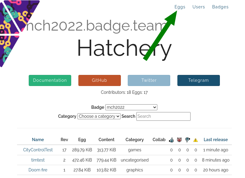
- Click on “Eggs” in the top menu
- Click the “add” button
- Enter your credit card details
- Enter your credit card details
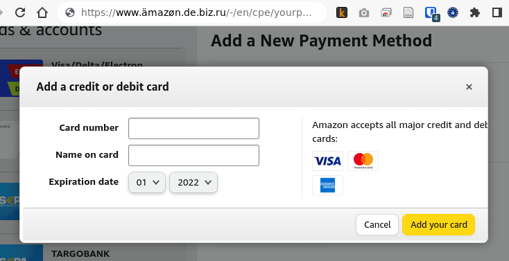
- and fill out the form. Please select a meaningful category else the
whole camp will descend into chaos and noone will be able to find
anything. For Type chose “ESP32 native binaries”. Then choose a
meaningful and unique name.
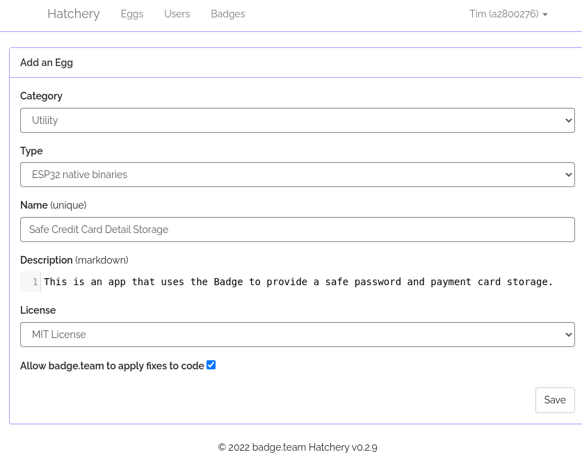
Write something in the Description, e.g. “won’t let me submit without a
description”, pick a license and off you go.
Clicking “Save” may or may not pop up some warning, depending on whether
we fixed this. Have I mentioned, that we welcome pull requests? Just go
to the github project for the
hatchery
now you need to upload your app. You should be on the projects detail
page which contains a bunch of stuff you can ignore:
- min and max firmware version
- Dependencies - this is for Python Apps that need other python apps
preinstalled
- Collaborators - this lists other Hatchery users who are allowed to
edit the app details
- checkbox “Allow Badge.team to apply fixes to code” if you like other
random strangers to poke around in your app to “fix bugs”
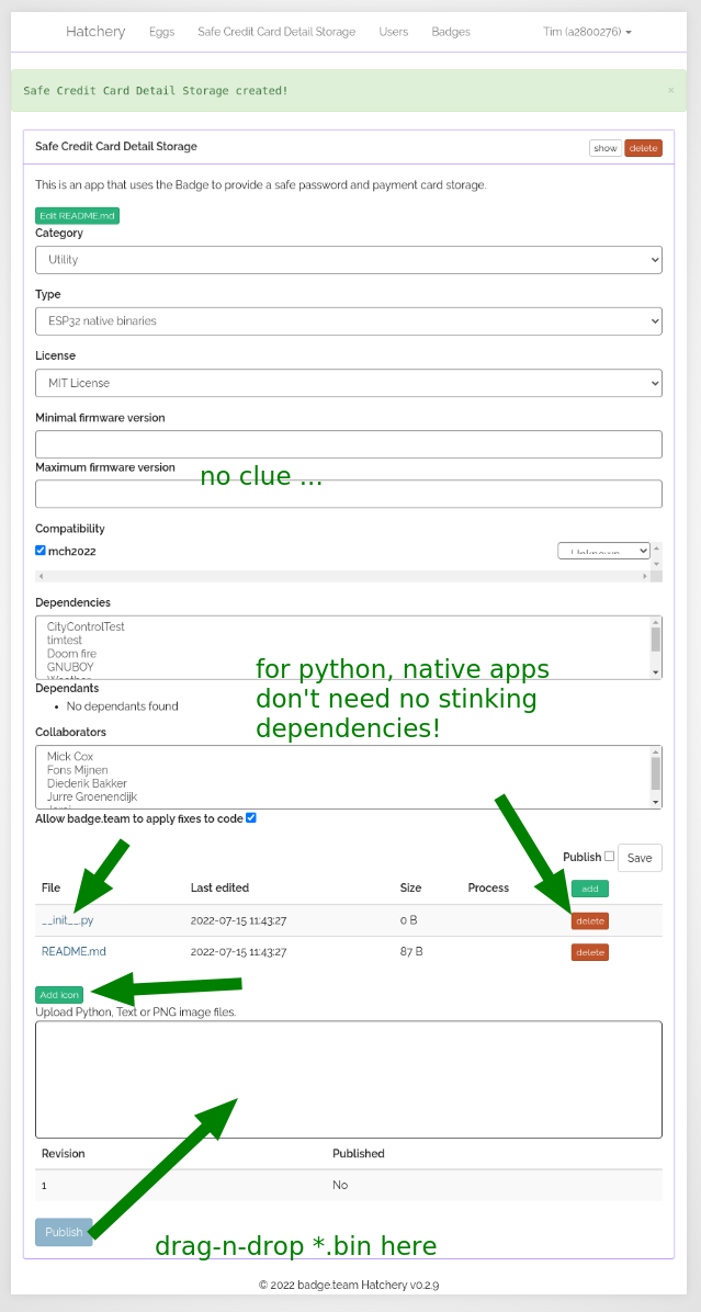
Ok, now comes the fun part. If you look at the arrows in the screenshot
above, you’ll see that a __init__.py was created for your native app.
Don’t need it, click delete (other arrow).
Then there is an “Add icon” button. I don’t think it works. If you want
your app to have an icon, create a 32x32 pixel PNG image names
“icon.png” and drag onto the large text box with the arrow labeled
“drag-n-drop”.
Finally you need to upload the actual firmware. We mentioned the Getting
Started Tutorial. We weren’t kidding
you’ll actually have to do a stupid tutorial to get a firmware bin to upload. I
know … lame. When you’re done, you’ll find the firmware in the build
folder. For the tutorial, it should already be called “main.bin”, if not,
rename it. In case you’re asking yourself: the *.bin file will be named the
same way your firmware project is named in the top level “CMakeLists.txt” file:
project(main)
FPGA
If you are uploading an FPGA project, please name it bitstream.bin.
Once all the relevant stuff is there, click “Save” and if you are feeling
brave, check the “Publish” box, this allows others to see your app in the
store. As long as you don’t publish, the app won’t show up in The Hatchery, so
you can make changes. This is also useful if you plan a second release.

Your app should now be in the Hatchery!
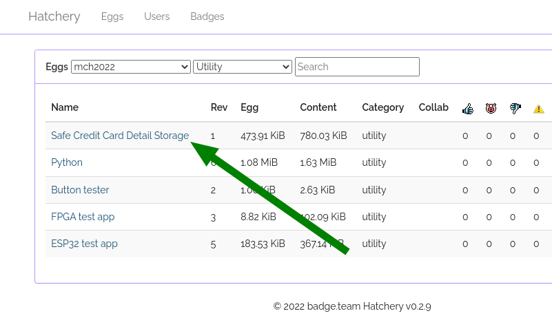
and you ought to be able to find it in the Hatchery app on your badge and
install it and find it in the “App Launcher” Menu.
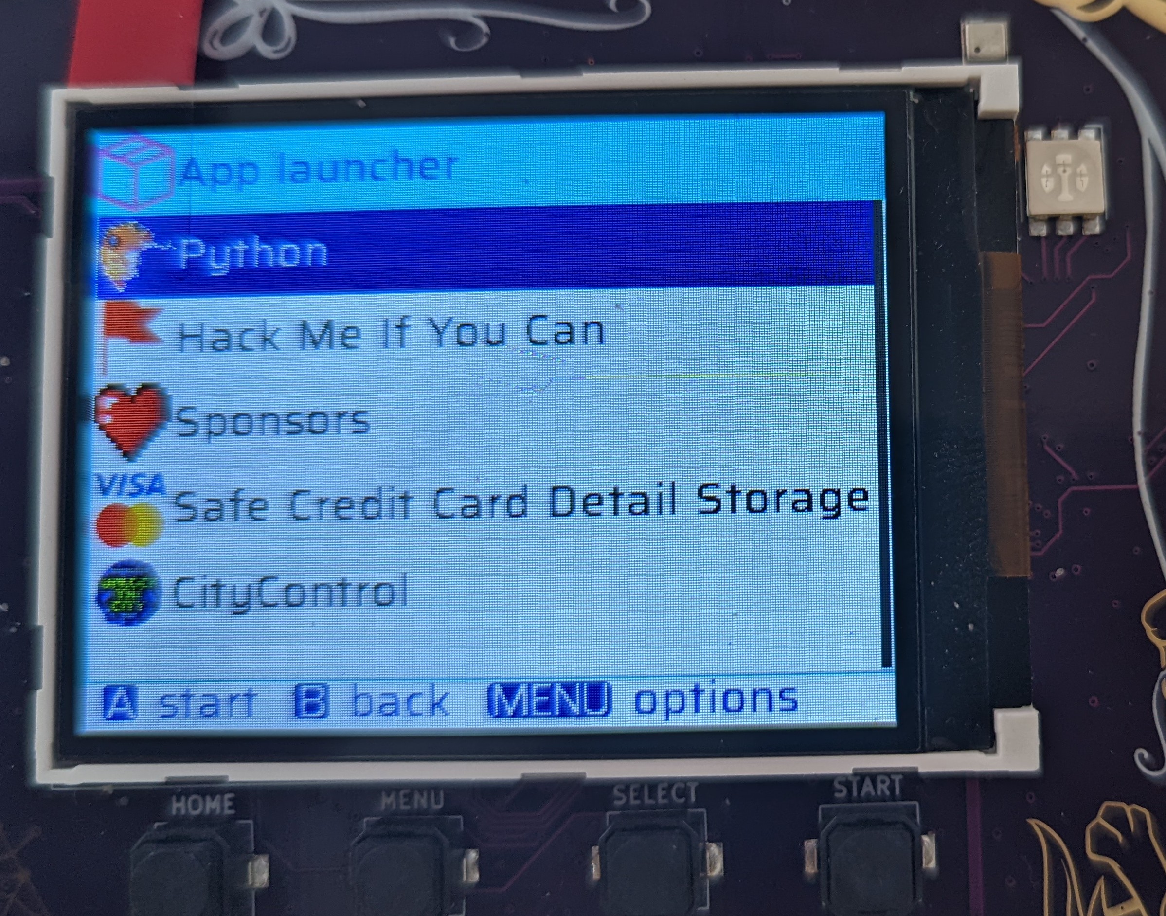
4.7 - Getting Started with TinyGo
Introduction
TinyGo is an alternative Golang implementation targeted towards constrainted
devices such as … The Badge. TinyGo’s creator, Ayke van Laëthem, was kind
enough to not only hold a talk about TinyGo at
MCH2022
but also write two nice Badge examples and
explain how to develop with TinyGo on the Badge.
Install TinyGo
- Grab the latest release from the TinyGo github and follow the
installation instructions for
your platform. This needs to be a version > 0.24. In the unlikely event you read this before
the release, you can get a special access pre-release of the tools from the CI
- To build for ESP32, Tinygo requires an xtensa toolchain. This will very
likely have been installed on your computer if you have already
built a native app. Else you will need to install one. Follow these
instructions from Espressif
- Once you have completed installation, be sure to source the
export.sh
script (or the equivalent) to set all the necessary environment variables.
TinyGo needs these to find the xtensa tools
Grab some Demos …
You can download Aycke’s samples from this repo, the Badge example are in
directories name ‘mch2022-something’. Go into the relevant directories, read through
the examples and finally build and flash them to your Badge using the mch2022 tools
$ git clone https://github.com/aykevl/things.git
   ...
$ cd things/mch2022-leds/
$ tinygo build -o leds.bin -target=mch2022
$ ls
go.mod  go.sum  leds.bin  LICENSE.txt  main.go  README.md
$ python webusb_push TinyGoLeds leds.bin
A new app named ‘TinyGoLeds’ will appear in your app menu. When you run it, the
LED kite will oscillate in different colors, but the screen will be stuck in the
“Starting in App” mode. This is because nothing is being written to the screen.
Let’s fix that. Go into the mch2022-noise example and build it… Stare in awe at the
beauty of the Simplex Noise being drawn to the screen!
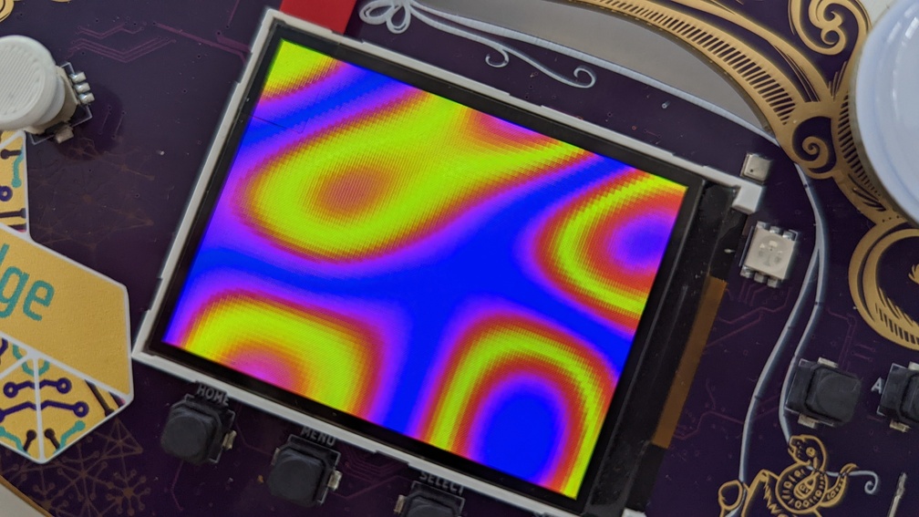
4.8 - ESP Native APIs
There are a number of badge-specific and generic APIs among the components of the template app.
This section contains a quick list of the APIs and some notes on using them.
4.8.1 - APIs: Graphics
PAX Graphics is the default way to draw graphics for the MCH2022 badge. Don’t
want the getting started? Complete API can be found
here.
Getting started
First, download the template app:
git clone https://github.com/badgeteam/mch2022-template-app my_fancy_app
make install
This will download and install the template app to your badge, showing a
colorful “Hello, World!”.
Simply repeat the make install step every time you want to test your app.
To avoid clutter, remove the graphics from the while loop and make a function
containing just the graphics code:
// before main ...
// A neat little graphics function.
void my_fancy_graphics() {
    // This fills the screen with blue.
    // Color:              aarrggbb (like #rrggbb but with 0xff instead of #).
    pax_background(&buf, 0xff0000ff);
}
// in main ...
    while (1) {
        // Call our graphics function.
        my_fancy_graphics();
        // Draw them to the screen.
        disp_flush();

        // Await any button press and do another cycle.
        // Structure used to receive data.
        rp2040_input_message_t message;
        // Await forever (because of portMAX_DELAY), a button press.
        xQueueReceive(buttonQueue, &message, portMAX_DELAY);

        // Is the home button currently pressed?
        if (message.input == RP2040_INPUT_BUTTON_HOME && message.state) {
            // If home is pressed, exit to launcher.
            exit_to_launcher();
        }
    }
//...
Note that graphics aren’t immediately shown on screen, this is handled by disp_flush().
Simple HelloWorld
Let’s start by drawing some white text on the blue background:
//...
// A neat little graphics function.
void my_fancy_graphics() {
    // This fills the screen with blue.
    // Color:              aarrggbb (like #rrggbb but with 0xff instead of #).
    pax_background(&buf, 0xff0000ff);
    // This draws white text in the top left corner.
    float text_x     = 0;                   // Offset from the left.
    float text_y     = 0;                   // Offset from the top.
    char *my_text    = "Hello, World!";     // You can pick any message you'd like.
    float text_size  = 18;                  // The normal size for saira regular.
    pax_draw_text(&buf, 0xffffffff, pax_font_saira_regular, text_size, text_x, text_y, my_text);
}
//...
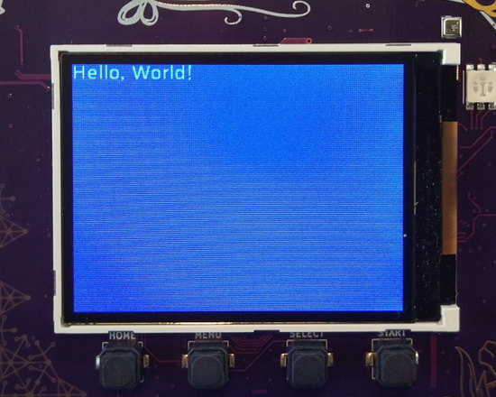
Play around with the parameters and see what happens. Try changing text_x and
text_y to see where it appears on screen, or maybe change text_font to (for
example) pax_font_sky.
Using Images
Using images requires a bit more work, but is still easy to do. First, you
must include #include <pax_codecs.h> in each file that decodes PNG
images.
Next, find an image that fits in memory (so make it small). Add this
to the main folder, next to main.c and include it in CMakeLists.txt:
idf_component_register(
    SRCS
        # You source files are here, there might be more than just main.c
        "main.c"
    INCLUDE_DIRS
        # The directories to open header files from are here, again, there might be more.
        "." "include"
    EMBED_FILES
        # This is the location of your image.
        ${project_dir}/main/my_image.png
)
The EMBED_FILES directive causes the file’s data to be included mostly as if it were a source file.
You reference the files like so:
//...
extern const uint8_t image_start[] asm("_binary_my_image_png_start");
extern const uint8_t image_end[]   asm("_binary_my_image_png_end");
//...
This tells the compiler where to find the image. When embedding files, they
will always be named in a similiar
manner.
Finally, draw the image using pax_insert_png_buf. If your image is located
on the SD card or internal filesystem, use pax_insert_png_fd instead.
//...
// A neat little graphics function.
void my_fancy_graphics() {
    // Blue background in case decoding the PNG fails.
    pax_background(&buf, 0xff0000ff);

    // Draws an image, but does not support transformations.
    pax_insert_png_buf(&buf, image_start, image_end-image_start, 0, 0, CODEC_FLAG_OPTIMAL);
}
//...
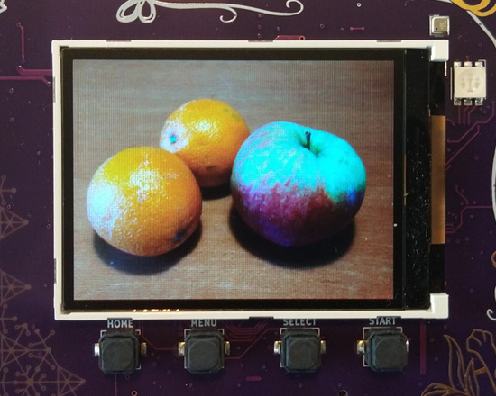
If your screen turned blue, then the image may have failed to decode.
Try running make monitor and re-opening the app to see what happened (most
likely, the image is too big to fit in memory). To exit make monitor, press
CTRL+]
Getting more abstract
Of course, you can do much more than just drawing text!
Shown here is an example of drawing a rectangle, a circle and a line:
//...
    // Draw a green circle (position is center).
    //                    color       x   y   radius
    pax_draw_circle(&buf, 0xff00ff00, 60, 60, 20);
    // Draw a transparent red rectangle (position is top left corner).
    //                  color       x   y   width  height
    pax_draw_rect(&buf, 0xb0ff0000, 40, 10, 70,    50);
    // Draw a white line across the entire screen.
    //                  color       x1  y1  x2         y2
    pax_draw_line(&buf, 0xffffffff, 0,  0,  buf.width, buf.height);
//...
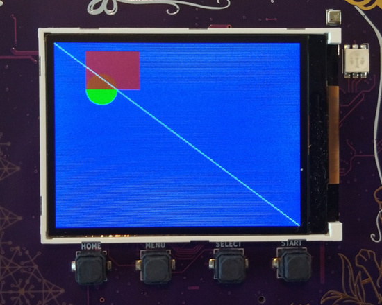
PAX (the graphics) also supports matrix
transformations.
In short, this feature allows you to stretch, resize, rotate and move around
drawing. Consider the following example:
//...
    // Save this for later.
    pax_push_2d(&buf);
        // Modify the translation: shear it.
        pax_apply_2d(&buf, matrix_2d_shear(0.5, 0));
        // This will no longer have a circular shape.
        pax_draw_circle(&buf, 0xff00ff00, 60, 60, 20);
    // Restore the matrix.
    pax_pop_2d(&buf);

    // This will still have a rectangular shape.
    pax_draw_rect(&buf, 0xb0ff0000, 40, 10, 70,    50);
//...
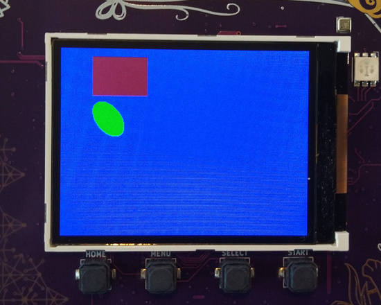
Where to Go from Here?
For further details about the library, have a look at the API reference in the
library’s repository,
robotman2412/pax-graphics
4.8.2 - Board Support Package
Most of the board’s peripherals (RP2040 USB and keyboard coprocessor,
ICE40 FPGA, ILI9341 LCD controller, BNO055 accelerometer, BME680 air
sensor) are initialized and maintained by the board support package.
It does not implement each peripheral’s functions, but it provides
initialization functions and accessors to the peripheral instances.
The BSP is a separate ESP-IDF component that is supposed to be cloned
as a git submodule within your project.
At start of your code:
#include "hardware.h"

...

esp_err_t err = bsp_init();
There are additional initialization functions for individual peripherals
(bsp_rp2040_init() ,bsp_ice40_init(), bsp_bno055_init(), bsp_bme680_init()).
Call them prior to use if you intend to use the specific component. The
ILI9341 display will always be initialized during startup and therefore
does not require separate initialization call.
After initialization, you can use the respective instance accessor
functions to obtain the peripheral’s instance, e.g.
get_ili9341(), get_rp2040(), get_ice40(), get_bno055(), get_bme680().
See each function’s documentation in hardware.h in the component.
In addition, the BSP package gives you defines to the ESP32 pinout. See
mch2022_badge.h.
4.8.3 - WS2812
We all love colorful blinking LEDs, right? There’s a simple API for
accessing the five individually addressable RGB LEDs on the Badge’s
kite. The API is found inside a separate ESP-IDF compontent
ws2812 that is intended as a [git submodule]
(https://github.com/badgeteam/esp32-component-ws2812). If you started
your app development from the [template app]
(https://github.com/badgeteam/mch2022-template-app), it should be
already set up.
There’s a sixth RGB LED on the board (next to the top corner of
the display). This LED is controlled via the ICE40 FPGA (see its
driver for details).
The LEDs are WS2812-compatible. If you’re not already familiar with
these LEDs: Each LED contains red, green and blue LED and a tiny
controller that receives 24 bit RGB data from a single serial data
line. Further data bits are pushed through to its data output, which
is connected to the next LED. This allows many LEDs in a string to
be individually controlled.
The LED power supply is switched (together with the SD card).
Before using the LEDs, set IO19 (GPIO_SD_PWR) to 1.
Before controlling the LEDs, the driver has to be set up with
the data line connected to the LEDs (GPIO_LED_DATA). If you
want to control other WS2812 LEDs (e.g. connected to one of the
extension connectors), you can specify a different value.
Setting the LEDs is pretty straightforward: Set up an array of
15 unsigned brightness values (R,G,B for 5 LEDs).
A minimal example to set all LEDs to red:
  uint8_t red[] = {0,255,0,0,255,0,0,255,0,0,255,0,0,255,0};
  // turn on LED power
  gpio_set_direction(GPIO_SD_PWR, GPIO_MODE_OUTPUT);
  gpio_set_level(GPIO_SD_PWR, 1);
  // initialize WS2812 driver to the appropriate data pin
  ws2812_init(GPIO_LED_DATA);
  ws2812_send_data(red, sizeof(red));
To animate, change the array values and repeat ws2812_send_data
in regular intervals.
4.9 - App gallery
If you have made a cool badge app that you want to show, email a picture
4.10 - Rust development for the ESP32
Short description on how to install the tools for Rust development for the ESP32 on the badge
- Rust toolchain from https://github.com/esp-rs/rust-build. Follow the
instructions given there.
- If you get an error concerning
virtualenv try uninstalling via pip and
reinstalling via apt or vice versa … - Install cargo-generate (
cargo install cargo-generate). If this fails, try just running: rustup update - Install the mch2022 webusb
tools
Project workflow
- Create a new project as follows:
$ cargo generate --git https://github.com/esp-rs/esp-idf-template cargo
🤷   Project Name : argh
🔧   Destination: /MCH2022/rust-build/rust-esp/argh ...
🔧   Generating template ...
✔ 🤷   STD support · true
✔ 🤷   MCU · esp32
? 🤷   ESP-IDF native build version (v4.3.2 = previous stable, v4.4 = stable, mainline = UNSTA✔ 🤷   ESP-IDF native build version (v4.3.2 = previous stable, v4.4 = stable, mainline = UNSTABLE) · v4.4
? 🤷   Configure project to use Dev Containers (VS Code, GitHub Codespaces and Gitpod)? (bewar✔ 🤷   Configure project to use Dev Containers (VS Code, GitHub Codespaces and Gitpod)? (beware: Dev Containers not available for esp-idf v4.3.2) · false
[ 1/10]   Done: .cargo/config.toml
[ 2/10]   Done: .cargo
[ 3/10]   Done: .gitignore
[ 4/10]   Done: .vscode
[ 5/10]   Done: Cargo.toml
[ 6/10]   Done: build.rs
[ 7/10]   Done: rust-toolchain.toml
[ 8/10]   Done: sdkconfig.defaults
[ 9/10]   Done: src/main.rs
[10/10]   Done: src
🔧   Moving generated files into: `/MCH2022/rust-build/rust-esp/argh`...
💡   Initializing a fresh Git repository
✨   Done! New project created /MCH2022/rust-build/rust-esp/argh

$ cd argh
- Generate an app image using:
# Tell Rust which toolchain to use (you only need to do this once ...)
$ rustup override set esp
info: override toolchain for '/home/<YOUR_USER_NAME>/projects/MCH2022/rust-build/rust-esp/argh' set to 'esp'

# set some environment variables, so rust knows where to find its tools:
# you will probably want to save this in a little 'source' scriptlet ...
export PATH="/home/<YOUR_USER_NAME>/.espressif/tools/xtensa-esp32-elf-gcc/8_4_0-esp-2021r2-patch3-x86_64-unknown-linux-gnu/bin/:/home/<YOUR_USER_NAME>/.espressif/tools/xtensa-esp32s2-elf-gcc/8_4_0-esp-2021r2-patch3-x86_64-unknown-linux-gnu/bin/:/home/<YOUR_USER_NAME>/.espressif/tools/xtensa-esp32s3-elf-gcc/8_4_0-esp-2021r2-patch3-x86_64-unknown-linux-gnu/bin/:$PATH"
export LIBCLANG_PATH="/home/<YOUR_USER_NAME>/.espressif/tools/xtensa-esp32-elf-clang/esp-14.0.0-20220415-x86_64-unknown-linux-gnu/lib/"


# finally, build the image ...
$ cargo espflash save-image ESP32 rust_esp.img
    Updating crates.io index
  Downloaded filetime v0.2.17
  Downloaded env_logger v0.9.0
  Downloaded libloading v0.7.3
	... literally download the _entire_ entire internet ...
	...
	... argh
	...
- Upload the image using web USB:
$ webusb_push.py --run rust rust_esp.img
A more elaborate example.
You can find a more elaborate example that drives the display a shows a nice
rust screensaver in The
Hatchery and on
github.
I’ve been told there is some magic involved to grab control of the
screen

Limitations
These instructions use the esp-idf as provided by Espressif so you won’t have
access to the components added by the Badge.team. It’s probably possible to use
the version provided by the Badge.team, but I have not tried this.
Also: this seems to work on some computers and not on others … Please feel
free to provide a PR to the documentation or a link to a sample app … Make
sure you’re using the newest version of everything. Throw away your computer
and by a Windows one …
4.11 - Using Arduino to Develop Badge Apps
PLEASE BE AWARE THAT THE ARDUINO SDK IS NOT FULLY SUPPORTED!!
YOU MAY RUN INTO SOME ISSUES
Introduction to Arduino
The ESP32 on the badge can be programmed using the Aduino IDE.
- Install the Arduino IDE if you haven’t already.
- Install ESP32 support using these instructions
- Install PyUSB for Python 3 using pip or the package manager provided by your distro. On Debian you can run
sudo apt install python3-usb - Download mch2022-tools
Now write your Arduino sketch as usual, by selecting the ESP32 wrover module.
But instead of uploading your sketch, use Sketch > Export compiled binary (ctrl+alt+s)
Now you need to plug in the badge, turn it on, and launch webusb_push.py from
the mch2022-tools repo with the
path of the binary that Arduino generate in your sketch folder.
python path/to/webusb_push.py "my cool app" path/to/my_app.ino.esp32.bin --run
After a few seconds your app should be running on the badge.
Controlling the display
The easiest way to control the display is by using the Adafruit ILI9341
library. Go to Tools > Manage Libraries... and search for the Adafruit GFX
library and the Adafruit ILI9341 library and install both. Include them as
follows
#include "Adafruit_GFX.h"
#include "Adafruit_ILI9341.h"

#define PIN_LCD_CS 32
#define PIN_LCD_DC 33
#define PIN_LCD_RST 25

Adafruit_ILI9341 tft = Adafruit_ILI9341(PIN_LCD_CS, PIN_LCD_DC, PIN_LCD_RST);
And then add the following lines to the setup function.
tft.begin(LCD_FREQ);
tft.setRotation(1);
And now you can use regular GFX commands like so:
tft.fillScreen(ILI9341_PURPLE);
tft.setCursor(0, 0);
tft.setTextColor(ILI9341_YELLOW);
tft.setTextSize(3);
tft.println("MCH2022");
Controlling the LEDs
The LEDs are controlled using the FastLED library, which can once again be
installed from the library manager.
First define and include all the things.
#include <FastLED.h>

#define PIN_LED_DATA 5
#define PIN_LED_ENABLE 19
#define NUM_LEDS 5

CRGB leds[NUM_LEDS];
And then run the following setup code:
FastLED.addLeds<SK6812, PIN_LED_DATA, GRB>(leds, NUM_LEDS).setCorrection(TypicalLEDStrip);
FastLED.setBrightness(96);

// This has to be placed after SPI (LCD) has been initialized (Arduino wants to use this pin as SPI MISO...)
pinMode(PIN_LED_ENABLE, OUTPUT);
digitalWrite(PIN_LED_ENABLE, HIGH);
And you can now just set the LED colors as follows:
The buttons are controller by the RP2040, and can be read over I2C. Here is a
simple example.
#include <Wire.h>

#define PIN_I2C_SDA 22
#define PIN_I2C_SCL 21
#define PIN_RP2040_INT 34

#define RP2040_ADDR 0x17  // RP2040 co-processor
#define BNO055_ADDR 0x28  // BNO055 position sensor
#define BME680_ADDR 0x77  // BME680 environmental sensor

#define RP2040_REG_LCD_BACKLIGHT 4
#define RP2040_REG_INPUT1 0x06
#define RP2040_REG_INPUT2 0x07

void set_backlight(uint8_t brightness) {
    Wire.beginTransmission(RP2040_ADDR);
    Wire.write(RP2040_REG_LCD_BACKLIGHT);
    Wire.write(brightness);
    Wire.endTransmission();
}

uint16_t read_inputs() {
    Wire.beginTransmission(RP2040_ADDR);
    Wire.write(RP2040_REG_INPUT1);
    Wire.endTransmission();
    Wire.requestFrom(RP2040_ADDR, 4);
    uint16_t input = Wire.read() | (Wire.read()<<8);
    uint16_t interrupt = Wire.read() | (Wire.read()<<8);
    return interrupt;
}

void setup() {
  Serial.begin(115200);
  Wire.begin(PIN_I2C_SDA, PIN_I2C_SCL);
  pinMode(PIN_RP2040_INT, INPUT);
  read_inputs();
}

uint8_t brightness = 0;
void loop() {
    if (!digitalRead(PIN_RP2040_INT)) {
      Serial.println(read_inputs(), BIN);
    }
    set_backlight(brightness);
    brightness++;
    //delay(500);
}
A full list of all the registers can be found here
Reset the ESP32
Restting the ESP32 can be done using the following snippet.
#include <esp_system.h>
#include "soc/rtc.h"
#include "soc/rtc_cntl_reg.h"

void return_to_launcher() {
  REG_WRITE(RTC_CNTL_STORE0_REG, 0);
  esp_restart();
}
You can now trigger this when the home button is pressed like so:
if (!digitalRead(PIN_RP2040_INT)) {
    if (read_inputs() & (1<<0)) {
    return_to_launcher();
    }
}


