TL;DR
git clone https://github.com/badgeteam/mch2022-tools/
git clone --recursive https://github.com/badgeteam/mch2022-firmware-ice40
python3 mch2022-tools/webusb_fpga.py mch2022-firmware-ice40/projects/Hello-World/hello_world.bin
If the TL;DR wasn’t wordy enough for you, try “FPGA Getting Started for Badgers with Tiny Brains” or read on!
If you look for a beginner friendly, graphical FPGA development suite: https://github.com/badgeteam/mch2022-icestudio
Welcome
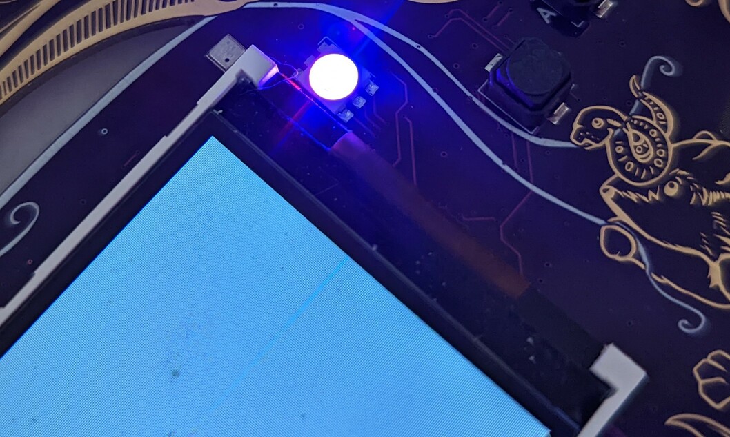
The badge contains an ice40 FPGA that is connected to a PMOD connector, a serial QSPI RAM, and a RGB LED. It can also control the display over a parallel bus, and has an USB UART link via the RP2040 and an SPI link to the ESP32 which notifies the FPGA on the state of the buttons and offers read access to large data files.
You can start with having a look at the top-level diagram of the badge hardware of the complete badge, then proceed to the schematic and pin constraints file.
Quickstart
As with all the other methods to program the badge, step one is to download
mch2022-tools.
There are two main tools to use here, python3 webusb_fpga.py bitstream.bin
which will upload a bitstream directly into the FPGA, and python3 webusb_fat_push.py bitsream.bin /sdcard/apps/ice40/myapp/bitstream.bin which
will make the bitstream available in the launcher.
The easiest way to install the tools needed to synthesise bitstreams for the FPGA is oss-cad-suite.
You can also build Yosys, Icestorm, and NextPNR from source.
Do not try to install packaged Yosys/NextPNR/Icestorm tools that might come with your distro – the toolchain is advancing very, very quick, and if your distro packaged it three months ago, it is already heavily outdated. The ones in Debian Stable – Ouch!
The main repository with templates and examples is
mch2022-firmware-ice40.
Running make in any of the folders in the projects directory should produce
a bitstream in separate build-tmp subfolder.
Also take note of the cores folder, which contains many useful
cores for basic functionality, such as providing the FPGA as a peripheral to
the ESP via SPI and others.
The FPGA can kind of be used in two seperate modes: standalone and peripheral mode.
Standalone
When launching a bitstream from the launcher, the ESP32 hands over control of the display to the FPGA, and exposes an API for reading buttons and files.
A simple example to read the buttons is found in buttons.v
A more elaborate example of a full-fledged RISC-V SoC with a wishbone bus and video output can be found in riscv_doom. While the example is runing Doom, but it’s actually a full featured RISC-V processor so it’s possible to change the RISC-V code running on it, add or modify peripherals on the wishbone bus, etc.
The file read interface
uses data files either temporarily uploaded along with the bitstream you are currently working on as webusb_fpga.py riscv-playground.bin 0xdabbad00:fw/tinyblinky/tinyblinky.bin or put into the filesystem as fpga_dabbad00.dat in the same folder as the bitstream itself.
You can use multiple data files with different 32-bit hexadecimal file identifiers.
Hints
If you want to think of the badge solely as FPGA dev board, you can ignore most of its other functionality, just keep in mind these handy hints:
The two UART lines are routed to
/dev/ttyACM1, your terminal program selects the baud rate.The FPGA should control the RGB LED using the SB_RGBA_DRV hard macro with constant current capabilities instead of a simple Verilog outputs, as that would overdrive at least the red LED.
The FPGA shall wait for then
lcd_modepin that switches between SPI/parallel mode of the LCD to go high before starting to talk to the LCD, as it is driven by the ESP32.Check twice before connecting external voltages to the PMOD :-)
Example projects for standalone mode
This is a list of Verilog examples available in https://github.com/badgeteam/mch2022-firmware-ice40/.
There is also a collection of examples written in Silice: https://github.com/sylefeb/mch2022-silice.
Blinkies
Three different blinkies are available for a bright first experience:
- Hello-World Completely new to FPGAs? Start here!
- Fading-White Smoother blinking than just on-off.
- Fading-RGB Smooth with colors!
Buttons
A small example on how to get the state of the buttons. This is not trivial as the buttons are not connected to the FPGA.
Ledcomm
A light emitting diode can shine, but it can also detect light. This contains an UART <-> Ledcomm bridge that allows one to transfer data between two badges just using a pair of LEDs. Still confused? Read the original paper https://merl.com/publications/docs/TR2003-35.pdf.
Forth Pmod Lab
Soldered something special for the Pmod connector? The Forth Pmod Lab helps you to quickly examine your hardware using the Forth language. Due to extensive documentation also suitable if you want to try Forth for the first time.
Snake
A free interpretation of the classic “snake” game with ASCII art and a Ledcomm based two-player mode. Enjoy!
RISCV-Playground
A complete beginner friendly RISC-V ‘fantasy microcontroller’ that deserves its own documentation.
Doom
Does it run Doom? Of course!
Peripheral mode
Both the C++ and the Python API contain a convenience function to load a bitstream into the FPGA from your ESP32 program. This allows the FPGA to be used as a peripheral for the ESP32 processor, think AI coprocessor, bitcoin mining, HDMI output…
A great way to get started with this is to use the spi_skeleton example, which exposes a wishbone bus to the ESP32 over SPI.
This mode could be used to add an UART port on the PMOD by adding the
following code, adjusting the top level ports and incrementing WN.
	// UART [2]
	// ----

	uart_wb #(
		.DIV_WIDTH(12),
		.DW(32)
	) uart_I (
		.uart_tx  (uart_tx),
		.uart_rx  (uart_rx),
		.wb_addr  (wb_addr[1:0]),
		.wb_rdata (wb_rdata[2]),
		.wb_we    (wb_we),
		.wb_wdata (wb_wdata),
		.wb_cyc   (wb_cyc[2]),
		.wb_ack   (wb_ack[2]),
		.clk      (clk),
		.rst      (rst)
	);
On the ESP32 you could then write the following Python script that loads a bitstream and writes to the newly added UART port.
import mch22
from fpga_wishbone import FPGAWB

# load bitstream from SD card onto the FPGA
with open("/sd/apps/ice40/myapp/bitstream.bin", "rb") as f:
    mch22.fpga_load(f.read())

# create a wishbone command buffer
c = FPGAWB()
# setup UART
# (30e6/9600)-2
c.queue_write(2, 4, 3123)
# queue writing a byte
c.queue_write(2, 0, 0xaa)
# queue reading a byte
c.queue_read(2, 0)
# execute the command queue
c.exec()
Example projects for peripheral mode
Selftest
Badge hardware ok next to the FPGA? The selftest checks for that and reports back to the ESP32.
SPI-to-RGB
The SPI to RGB bridge gives the ESP32 control over the RGB LED, which is directly connected to the FPGA.
Guide for complete newbies to FPGAs
Let’s try for short:
For a bunch of TTL logic chip to do something useful, you need to wire them up - and the way you wire these determines the function of the completed circuit.
A “Field Programmambe Gate Array” contains a grid of “universal gates” called lookup-tables with -in our case- 4 binary inputs and 1 output, and every of these is accompanied by 1 flipflop bit. Nothing special so far. The special sauce of an FPGA is their connection - that there is a dense mesh of wires in different lengths that crisscross the entire chip, with switchbox points that allow to choose how to connect the individual logic elements to the mesh of wires. By selecting which switchboxes to activate, one builds an actual digital circuit on the FPGA.
For your curiosity, here is a DIY FPGA: http://blog.notdot.net/2012/10/Build-your-own-FPGA
You should have an idea by now! You are going to build logic circuits. And you’ll probably fall into a rabbit hole :-)
Check out our “FPGA Getting Started for Badgers with Tiny Brains” guide for step by step information getting from 0 to a hardly working FPGA setup, in case you never heard of FPGAs before.
We would love to give you a more complete intro, but for time-is-not-infinite reasons, recommend you intros from others instead.
For the ones that prefer reading and want to know everything to design their own RISC-V CPU at the end of the course:
https://github.com/BrunoLevy/learn-fpga/tree/master/FemtoRV/TUTORIALS/FROM_BLINKER_TO_RISCV
For the ones that prefer videos and a calm pace, Shawn Hymel has done a series in 12 parts that really starts at the beginning and explains the scenery you encounter:
https://github.com/ShawnHymel/introduction-to-fpga https://www.digikey.de/en/maker/projects/introduction-to-fpga-part-1-what-is-an-fpga/3ee5f6c8fa594161a655a9f960060893

