Sometimes the wheel gets reinvented again, again and again. This is a collection of stuff that could be useful if you’re designing a badge or accessories for badges.
1 - Battery
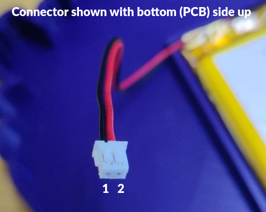
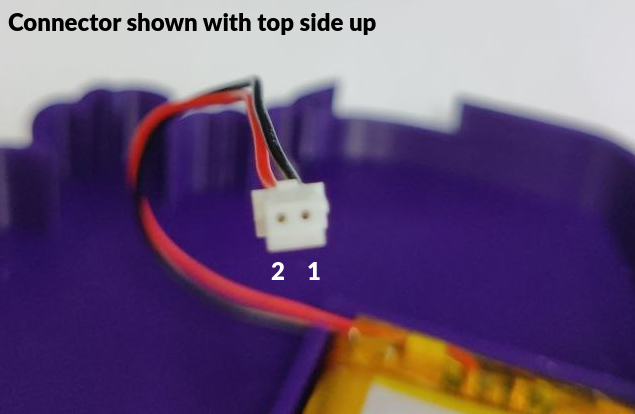
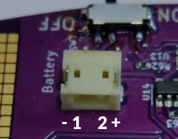
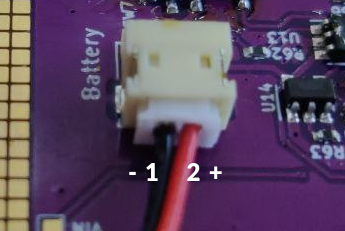
We use the JST S2B-ZR-SM4A-TF connector on our badges. This connector has two pins at 1.5mm pitch.
Pinout
| Pin | Function | Wire color |
|---|---|---|
| 1 | GND | Black |
| 2 | Vbatt | Red |
Photos
2 - SAO: Standardized Add-On
The Standardized Add-On connector is a standardized way of connecting boards with additional functionality to badges, allowing for add-on boards to work with a variety of badges and for the users of badges to enjoy a variety of add-ons.
History
This standard started out as a bit of a joke, with the Shitty Add-On standard published in a hackaday.io project by Brian Benchoff and was later revised in the Shitty Add-On v1.69bis standard (also by Brian Benchoff).
While the SAO 1.69bis standard defines the electrical characteristics of the addons it does not provide any usable method for identifying what addon has been connected. The solution for this shortfall can be found in the badge addon id standard by Uri Shaked. The identification method referred to by the v1.69bis standard is this unusable identification data structure described by AND!XOR.
Our new standard
Badges are serious fun and serious fun of course needs to be constrained by serious specifications. Because of this we’re introducing the Standardized Add-On v4.2terbo standard. It’s guaranteed to improve compatibility and it might also somehow be faster, who knows?
SAO
The connector
A SAO is connected to the badge via a two row, three columns (2x3) 2.54mm (or 0.1" for those refusing practical units) pitched female socket which mates with the standard 2x3 male header that most hackers already have in their toolboxes. If possible a keyed connector should be used on the badge, which will in combination with a shrouded header on the addon board prevent users from plugging in the addon in a wrong orientation or position.
| Pin | Function | Notes |
|---|---|---|
| 1 | 3.3v power | Provides power to the add-on, do not feed back power into a connected badge |
| 2 | GND | Reference |
| 3 | SDA | I2C data |
| 4 | SCL | I2C clock |
| 5 | GPIO1 | General purpose in- or output pin 1. Also used as data pin for connected WS2812 (Neopixel) and APA102 (DotStar) addressable LEDs |
| 6 | GPIO2 | General purpose in- or output pin 2. Also used as clock pin for APA102 (DotStar) addressable LEDs and as interrupt input |
Identification
To allow for automatic identification an addon can provide an EEPROM at I2C address 0x50.
Both small (8-bit address length) and bigger (32-bit address length) EEPROMS can be used, but keep in mind that people can accidently overwrite data in small eeproms because these devices interpret a read from a 16-bit address as a write command. Because of this enabling the write-protect feature of smaller identification EEPROMs is strongly recommended.
Safe identification
First attempt an 8-bit read of 4 bytes starting at memory address 0x00 of the EEPROM at I2C address 0x50. The first byte is to be ignored and the second, third and fourth bytes are to be compared against the header identification table. If no match is found proceed with a 16-bit read of 4 bytes starting at address 0x00 of the EEPROM at I2C address 0x50, again compare the second, third and fourth bytes are to be compared against the header identification table. If again no match is found the SAO is to be determined unformatted and further automatic communication must be avoided. Optionally the user may be prompted to format the addon.\
Ignoring the first byte read from the EEPROM is done to allow for identifying addons for which the first EEPROM byte was corrupted by an accidental write caused by a 16-bit read command sent to an EEPROM using 8-bit addresses.
Header identifiers
| 1 | 2 | 3 | 4 | Description | Documentation |
|---|---|---|---|---|---|
| L | I | F | E | Binary descriptor | On this site |
| J | S | O | N | JSON text descriptor | |
| T | E | A | M | Reserved for Badge.team use |
2.1 - Binary SAO descriptor
This document describes the header format used in the identification EEPROM at address 0x50.
Header
The header contains a magic value to identify the SAO as having a binary header. This header is always the ASCII characters for “LIFE”. We recommend badges only check the last three bytes (“IFE”) to identify small EEPROM chips which got their first byte corrupted. In case the first byte is found to be corrupted we recommend the badge corrects the faulty first byte by writing an “L” to address 0.
Then follows the length of the SAOs name as a single byte. The name itself follows directly after the header. as ASCII text, the name can be at most 255 characters long. We recommend to only use visible 7-bit ASCII characters in the name to ensure compatiblity.
The functions of the SAO can be described using drivers. The drivers supported vary between different badges. If an unsupported driver gets detected it can be ignored by the badge. The identifier of the first driver is described in a similar way to the name of the SAO itself: a length byte. The name itself follows after the SAO name as ASCII text.
The last field of the header tells the badge the number of additional drivers available on the SAO. Not all badges support additional drivers. If no additional drivers are available for the SAO this field must be set to 0. Additional driver data is appended after the main header.
Example
| Offset | 0 | 1 | 2 | 3 | 4 | 5 | 6 | 7 | 8 | 9 | 10 | 11 | 12 | 13 | 14 | 15 | 16 | 17 | 18 | 19 |
| Description | Magic | Name length | Driver name length | Driver data length | Number of extra drivers | Name | Driver name | Driver data | ||||||||||||
| HEX | 4C | 49 | 46 | 45 | 05 | 04 | 03 | 00 | 48 | 45 | 4C | 4C | 4F | 74 | 65 | 73 | 74 | 01 | 02 | 03 |
| ASCII | L | I | F | E | H | E | L | L | O | t | e | s | t | |||||||
This header defines a SAO named “HELLO” which has support for driver “test”. The SAO contains three bytes of information for use by the “test” driver, namely 0x01 0x02 0x03. There are no additional drivers.
Additional drivers
Additional drivers add extra header fields describing each driver.
| Offset | 0 | 1 | 2 | 3 | 4 | 5 | 6 | 7 | 8 |
| Description | Driver name length | Driver data length | Driver name | Driver data | |||||
| HEX | 04 | 03 | 74 | 65 | 73 | 74 | 01 | 02 | 03 |
| ASCII | t | e | s | t | |||||
Drivers
The following drivers are supported by the MCH2022 badge:
- Storage: describes the unused EEPROM memory available on the SAO
- Basic I/O: describes buttons and LEDs connected to the SAO GPIO pins
- Neopixel: describes addressable LEDs connected to the SAO GPIO pins
- ssd1306: describes an SSD1306 OLED display connected to the I2C bus
- ntag: describes an NTAG NFC tag connected to the I2C bus
- app: describes the name of a companion app
Documentation for these drivers has yet to be written. More information can be found in the firmware source code here: Github